
Electronic Door Buzzer

The described circuit functions as a simple audio oscillator that generates sound through a feedback mechanism involving an operational amplifier. When the switch SI is activated, it allows current to flow, charging capacitor C2. The initial application of voltage to the non-inverting terminal of U1 sets the stage for oscillation. The operational amplifier, configured in a feedback loop, begins to oscillate at a low frequency determined by the values of resistors and capacitors in the circuit.
As C2 charges through resistor R3, the voltage across C2 increases, which in turn affects the input to the operational amplifier. The change in voltage causes the frequency of oscillation to increase rapidly. The relationship between the charging time constant of C2 and the resistance of R3 is crucial in determining the frequency shift. The rapid increase in frequency results in a higher-pitched sound output at the speaker SPKR1.
The speaker converts the electrical oscillations into audible sound waves. The design ensures that the generated sound is of a frequency that can easily cut through background noise, making it effective for signaling or alerting purposes in various applications. This circuit can be utilized in alarm systems, toys, or any application where an audible alert is required. Proper selection of component values will allow for tuning the circuit to achieve desired frequency ranges and sound characteristics. When SI is depressed, an initial positive voltage is placed on C2 and the noninverting terminal of Ul. The circuit o scillates at a low frequency. As C2 charges up through R3, a rapid increase in frequency of oscillation results, producing (at SPKR1) a rapidly rising pitched sound. This sound is easily recognized over ambient noise.
Related Circuits
This very simple and self-powered device was conceived to allow a person to monitor if someone has rung his home door-bell when he was out. As most door-bells use 12Vac supply, the circuit must be simply connected to the...

This circuit is easily identifiable by three equal-value capacitors and two equal-value resistors connected to the base of the transistor. The output signal of a transistor in COMMON EMITTER mode is FALLING when the input signal is RISING, which...

An 8-ohm speaker functions as both a microphone and an output device. The BC109C transistor operates in common base mode, providing substantial voltage gain while ensuring a low impedance input suitable for the speaker. Self DC biasing is implemented...
This circuit provides a delayed visual indication when a door bell switch is pressed. In addition, a DPDT switch can be moved from within the house which will light a lamp in the door bell switch. The lamp can...
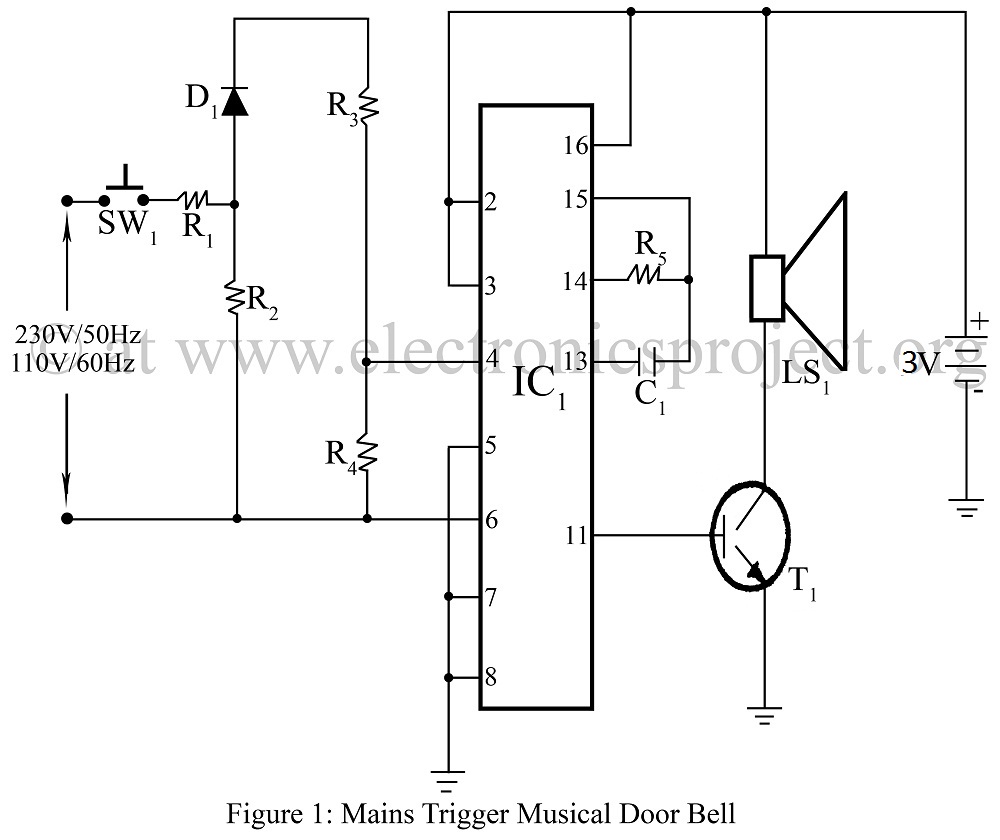
Mains-triggered musical doorbell using the musical IC UM3482 circuit diagram, featuring various and unique doorbell projects. The mains-triggered musical doorbell circuit utilizes the UM3482 integrated circuit, which is specifically designed for generating musical tones. This circuit is activated by a...

A simple supercapacitor charger electronic project can be designed using the LTC3625 integrated circuit (IC) from Linear Technology. This circuit is capable of charging two supercapacitors in series to a fixed output voltage of either 4.8V/5.3V or 4V/4.5V, which...