
Supercapacitor charger electronic circuit using LTC3625

The LTC3625 is a high-performance buck-boost converter designed specifically for supercapacitor charging applications. Its ability to operate over a wide input voltage range makes it suitable for various power sources, including batteries and solar panels. The device's efficiency is critical, as it ensures that most of the input power is converted into usable output energy, minimizing losses during the charging process. The fixed output voltage selection allows for flexibility in applications, enabling the user to adapt the circuit to different supercapacitor configurations.
The automatic cell balancing feature of the LTC3625 is particularly advantageous, as it ensures that both supercapacitors charge equally, thus extending their lifespan and maintaining performance. This is achieved without the need for external balancing resistors, which can introduce additional complexity and power loss. Instead, the LTC3625 internally manages the balancing process, allowing for a more compact and efficient design.
The choice of an LT1784 operational amplifier in this circuit further enhances performance. The LT1784 is known for its low offset voltage and low noise characteristics, making it ideal for precision applications where accurate voltage levels are crucial. This op-amp can be used in feedback loops or signal conditioning stages within the circuit, contributing to the overall stability and reliability of the supercapacitor charging process.
Overall, this supercapacitor charger circuit is a robust solution for energy storage applications, combining high efficiency, ease of use, and minimal component requirements. The design is particularly suited for renewable energy applications, such as solar energy systems, where effective energy storage is essential for continuous power supply. The simplicity of the circuit allows for easy integration into various projects, making it an excellent choice for both hobbyists and professionals in the field of electronics.A very simple supercapacitor charger electronic project can be designed using the LTC3625 IC designed by Linear technology to charge two supercapacitors in series to a fixed output voltage (4. 8V/5. 3V or 4V/4. 5V selectable) from a 2. 7V to 5. 5V input supply. Automatic cell balancing prevents overvoltage damage to either supercapacitor while maximizi ng charge rate without using any balancing resistors. This electronic circuit project presented in this circuit diagram has high efficiency, high charging current, low quiescent current and require low minimum external parts Charging current/maximum input current level is programmed with an external resistor. When the input supply is removed and/or the EN pin is low, the LTC3625 automatically enter a low current state, drawing less than 1 A.
The circuit is very simple requiring few external electronic parts, excepting the LTC3625 IC and solar panel this circuit project require a LT1784 op amp and some common external parts. 🔗 External reference
Related Circuits

This inverter circuit is designed to power electric razors, stroboscopes, flash tubes, and small fluorescent lamps using a 12-volt car battery. Unlike conventional feedback oscillator inverters, this design features a separate oscillator from the output stage, allowing for easy...
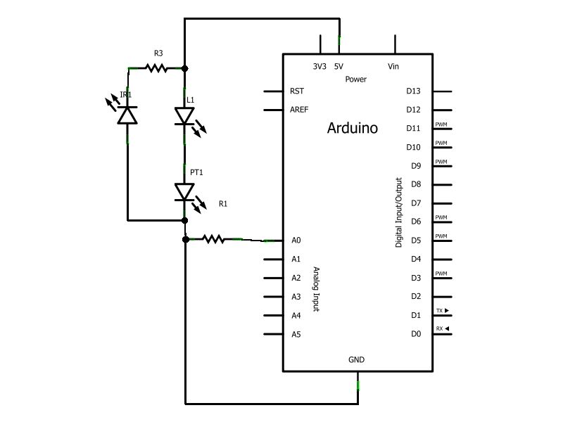
Have you ever wanted to create a line-following robot but found infrared sensors too expensive? If you are located in the UK and have access to a Maplin store nearby, you can purchase infrared transmitters and receivers for just...
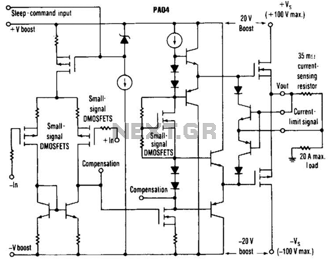
This circuit from Apex Microtechnology can deliver 180 V peak-to-peak at 90 kHz into a 4-ohm load. The PA04 can deliver 400 watts RMS into an 8-ohm load with low total harmonic distortion at frequencies exceeding 20 kHz. The circuit...
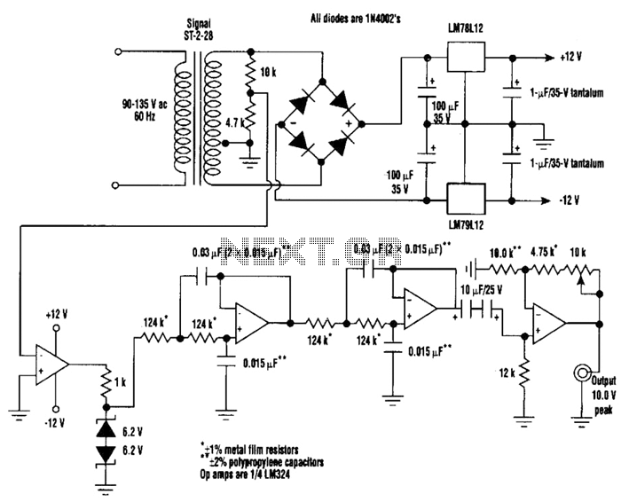
A highly stable 60-Hz sine wave can be delivered with this circuit, which offers a different and much simpler approach to achieving a stable amplitude. Capacitor coupling in the last stage removes any DC component caused by unequal Zener...
This application note outlines the functionality of the MAX4929E, which manages the switching of all low-frequency signals (LoF) required for a 2:1 HDMI/DVI switch while providing high-level ESD protection for all external lines. It also details how the MAX4929E...
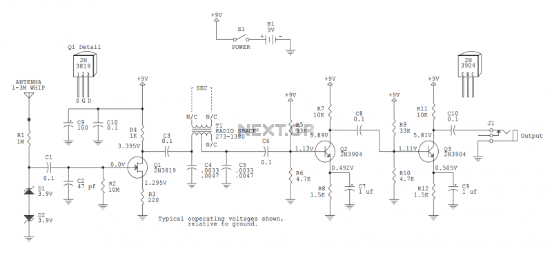
This version sports a 2nd audio amplifier stage at Q3. The output level with this version is sufficient to drive a crystal headphone to a comfortable volume. The "crystal" headphone is like those used on ye olde crystal radios....