
Electronic lark sounds circuit

The described electronic circuit utilizes a sound synthesis approach to emulate the vocalizations of birds, responding dynamically to ambient lighting changes. The core component of this circuit is a microcontroller or sound generator IC, which is programmed to produce different sound patterns resembling various bird calls. The microcontroller receives input from a light sensor, such as a phototransistor or a light-dependent resistor (LDR), that detects the intensity and type of ambient light, particularly neon lighting.
As the light intensity varies, the microcontroller processes this information and adjusts the output sound frequency and modulation accordingly. This results in a range of tones that mimic the natural variability of bird sounds, creating an engaging auditory experience. The circuit may include additional components such as capacitors for filtering, resistors for biasing, and possibly a digital-to-analog converter (DAC) if high-fidelity sound reproduction is required.
Power supply considerations are also essential, as the circuit must operate efficiently under varying conditions. A regulated power supply, possibly utilizing a battery or an AC adapter, ensures stable operation of the microcontroller and sound output components.
The schematic diagram of this circuit should clearly illustrate the connections between the light sensor, microcontroller, sound output module (such as a speaker or piezo buzzer), and the power supply. Proper grounding and decoupling capacitors should be included to minimize noise and ensure reliable operation.The electronic circuit birds under different lighting, especially in the vagaries of the neon light irradiation, can be issued fluctuated, changing tone sound of birds, the sound is constantly changing. Its circuit is shown.
Related Circuits
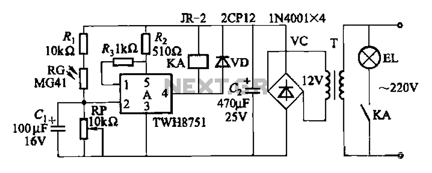
The adjustment potentiometer RP can modify the sensitivity of the device. Capacitors C1 function as an anti-light interference mechanism for instantaneous action. The adjustment potentiometer (RP) is a variable resistor that allows for fine-tuning of the device's sensitivity. By altering...
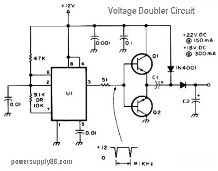
The schematic diagram originates from a 12V DC voltage doubler circuit power supply. This circuit diagram illustrates a DC voltage doubler/DC converter that transforms a 12V DC power supply into 24V DC and 18V DC outputs. It is compatible...
The circuit diagram represents a water-activated relay circuit. This circuit employs two transistors configured as a high-gain compound pair. The transistors used are 2N2222A for T1 and T2, which may also be substituted with BC108. The current gain is...
This circuit is a simple IR detector for testing IR remote controllers. The circuit is based on one phototransistor which receives the IR beam. The NPN transistor works as an amplifier which feeds current to the LED. When this...

An LM311 comparator converts a small analog signal to a digital level for the DC4046 phase-locked loop, which is configured as a first-order FM demodulator. This demodulator operates with a 50-kHz FM modulated input signal and has applications in...
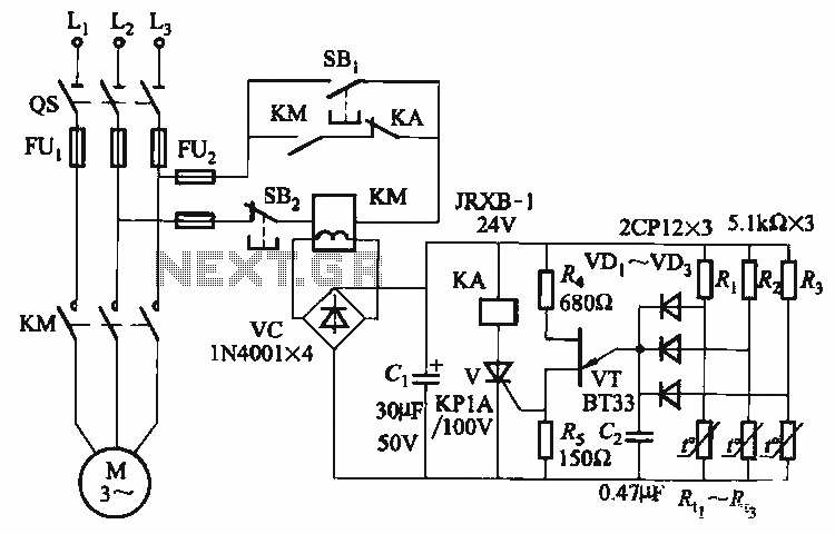
The thyristor control circuit includes a bridge circuit designed to regulate the temperature in the contactor coil KM, along with a secondary winding that functions as a power protection device. It comprises a thermistor (R:., Rt3) and a resistor...