
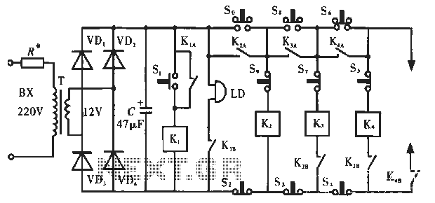
Electronic Lock with 4013

The described circuit operates as a sequential lock system utilizing momentary push-button switches. The primary function is to unlock a mechanism connected to the K1 load, which could represent an electronic lock or relay. The operation relies on pressing the switches in a predetermined order: S1, S2, S3, and S4.
In terms of design, the circuit typically consists of four momentary switches, each connected to a microcontroller or a logic circuit capable of recognizing the sequence of inputs. The microcontroller is programmed to monitor the state of each switch. When a switch is pressed, the microcontroller checks if it is the expected switch in the sequence. If the correct switch is pressed, the microcontroller proceeds to the next expected switch in the sequence.
If an incorrect switch is pressed at any point, the microcontroller triggers a reset condition, which may involve turning off the K1 load and restarting the sequence. This ensures that only the correct sequence will successfully activate the lock mechanism.
To enhance flexibility, the circuit can be designed to accept any combination of four switches, allowing customization based on user preference. The wiring of the switches can be configured in parallel or series, depending on the desired behavior of the circuit.
Additional components may include resistors for pull-down or pull-up configurations to ensure stable switch readings, as well as diodes to prevent back EMF if inductive loads are used. The output to the K1 load can be managed through a transistor or relay, providing a safe interface between the low voltage control circuit and the higher voltage lock mechanism.
In summary, this basic sequential lock circuit offers a simple yet effective method for controlling access based on a specific sequence of user inputs, ensuring security and flexibility in operation.This circuit is very basic to build. To open a the lock which is connected to the K1 Load you must press each momentary switch in the correct sequence. The sequence used in this circuit is S1,S2,S3,S4. If any of the other switches are pressed the circuit will reset and you will need to start over. Depending on how you wire the switches, you can use any 4 switch combination. 🔗 External reference
Related Circuits
This precise one-pulse-per-second clock is constructed using a few common components and is driven by a 50 or 60 Hertz mains supply, without any direct connection to it. It produces a beep or metronome-like click and/or a visible flash...
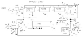
This 860 MHz Phase Locked Loop (PLL) oscillator circuit is designed for a 1200 MHz transverter's local oscillator with 435 MHz rigs. The oscillator circuit utilizes Toshiba PLL synthesizer ICs. The TC9122P is a user-friendly preset counter for determining...
A schematic diagram of the oscillator is presented in Figure 1. The common-base transistor stage (Q1) amplifies the signal within the positive feedback loop. The positive feedback signal develops across the resistor R1, which is shared by the emitters...
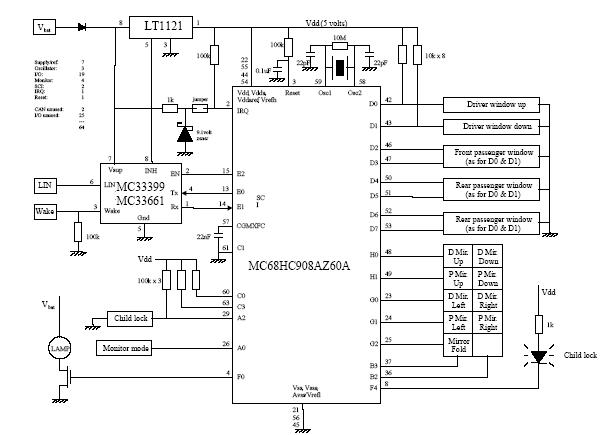
The following circuit illustrates a Car Door Keypad Electronic Circuit Diagram. Features include a lower pin-count and a cost-effective design utilizing the MC68HC908AZ60A microcontroller. The Car Door Keypad Electronic Circuit is designed to enhance vehicle security by providing a user-friendly...
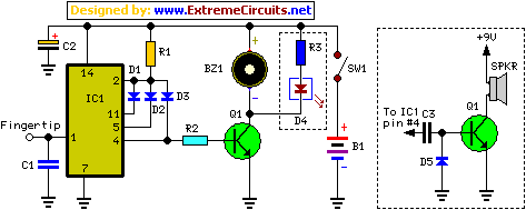
The circuit operates as illustrated in Figure 5-2a. It includes an alarm switch (S). When switch S is pressed, relay K is activated, which closes two normally open contacts. This action triggers the alarm bells. The alarm continues to...
This metal detector circuit project is a simple design based on common electronic components. It utilizes transistors to provide a visual indication through an LED and an acoustic signal to alert users when metal is detected. To calibrate the...