
Electronic Organ Circuit

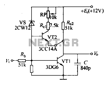
The electronic organ circuit utilizes an emitter-coupled oscillator configuration, which is known for its stability and simplicity in generating square wave signals. In this design, transistors T2 and T3 are configured to operate in an oscillator mode, where the feedback from the collector of T3 to the base of T2 ensures continuous oscillation. The output signal, taken from the collector of T3, is characterized by its square wave form, which is essential for creating the desired tone.
To enhance the sound quality, a vibrato effect can be integrated into the circuit. This is achieved through the inclusion of switch S1, which allows the user to enable or disable the vibrato feature. The vibrato effect modulates the pitch of the output signal at a frequency of approximately 6 Hz, providing a richer auditory experience. The amplitude of this vibrato modulation is adjustable through resistor R4, which acts as a variable resistor in the circuit. By selecting different values for R4, ranging from 100 ohms to 300 kilohms, users can tailor the intensity of the vibrato effect to their preference.
Overall, this electronic organ circuit offers a simple yet effective means of generating musical tones with the added flexibility of vibrato modulation, making it suitable for various applications in electronic music production and sound design.This electronic organ circuit is very simple to construct and is basically an emitter-coupled oscillator composed of T2 and T3. An squarewave voltage can be sampled from the collector of T3 (X2). This signal gives a clarinet character to the tone. An additional vibrato signal can be added to this basic sound through switch S1. The frequency of the vibrato is around 6 Hz. Its amplitude is determined by the R4. The value of R4 can vary from 100 up to 300K © but you can experiment with different values. 🔗 External reference
Related Circuits
Electronics tutorial on mesh current analysis and examples of mesh analysis used to analyze complex electrical circuits in DC theory. Mesh current analysis is a powerful technique used in circuit analysis to determine the currents flowing in the loops of...
The circuit consists of an ultrasonic transmitter and a receiver that operate at the same frequency. Ultrasonic piezoelectric transducers serve as the output and input devices, respectively, with their frequency of operation determined by the specific devices used. The...

This circuit represents a negative resistance configuration. All previous circuits utilize RC time constants to achieve resonance. LC combinations can also be employed, providing good frequency stability, high Q factor, and rapid startup. In this circuit, a signal input...
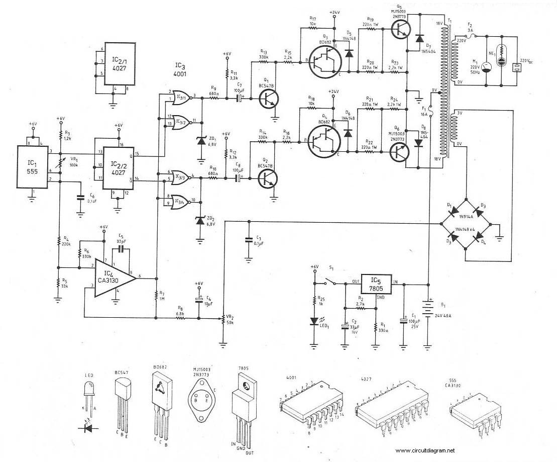
This is the schematic diagram of a 300W power inverter circuit. The inverter utilizes the MJ15003 power transistor for final amplification. If the MJ15003 transistor is difficult to source, it can be replaced with a 2N3773. The inverter is...
Various sawtooth voltage generators utilize the principle of capacitor charging and discharging to produce sawtooth waveforms in both forward and reverse directions. A simple sawtooth voltage generator circuit is straightforward in design; however, it suffers from poor linearity in...
The circuit includes a comprehensive array of components such as vibration sensors, a follower, a lamp relay control circuit, a voice sounding circuit, a high-frequency oscillation circuit, and an AC rectifier buck power supply circuit. The vibration sensor is...