
Mesh Current Analysis - DC Circuit Theory

Mesh current analysis is a powerful technique used in circuit analysis to determine the currents flowing in the loops of an electrical circuit. This method is particularly useful for analyzing complex circuits that can be represented in a planar format, allowing for the application of Kirchhoff's Voltage Law (KVL). The fundamental principle involves assigning a mesh current to each independent loop in the circuit and forming a set of equations based on KVL.
To apply mesh current analysis, follow these steps:
1. Identify the meshes in the circuit. A mesh is defined as a loop that does not contain any other loops within it.
2. Assign a mesh current to each identified mesh. The direction of the mesh current can be chosen arbitrarily, but it is common to assume a clockwise direction.
3. Apply KVL to each mesh. This involves summing the voltage drops and gains around the loop and setting the sum equal to zero. Each voltage drop across a resistor can be expressed as the product of the resistance and the current through it, while voltage sources contribute directly to the KVL equation.
4. Solve the resulting system of equations simultaneously to find the values of the mesh currents.
Examples of mesh analysis can include circuits with multiple resistors, voltage sources, and current sources. When analyzing such circuits, it may be necessary to express the mesh currents in terms of a reference node or ground, especially when dealing with dependent sources or when the circuit is not purely resistive.
Mesh current analysis is especially advantageous for circuits with many components, as it reduces the number of equations needed compared to node voltage analysis. Additionally, it allows for a systematic approach to solving for unknown currents and voltages, making it an essential tool for electronics engineers and students studying DC circuit theory. By mastering this technique, one can effectively analyze and design complex electrical circuits.Electronics Tutorial about Mesh Current Analysis and Mesh Analysis Examples used to Analyse Complex Electrical Circuits in DC Theory.. 🔗 External reference
Related Circuits
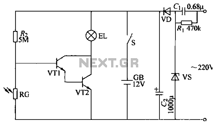
The power supply circuit features a step-down capacitor (C1), bleeder resistors (R), a Zener diode (VS), a full diode (VD), and a filter capacitor (G), along with switches and batteries (GB, SC). The light control circuit is composed of...
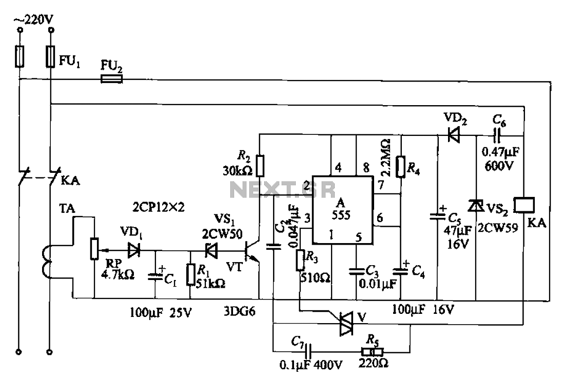
The 555 limit circuit, which is an integrated electrical circuit, is designed to manage large electrical loads. It automatically disconnects power when the load exceeds a predetermined threshold. Once the load is reduced below this threshold, power is restored...
Many applications require low-frequency signal generators that can deliver high-performance, high-resolution signals. This design idea presents a circuit that generates frequencies from 0 to 1 MHz, providing sinusoidal, triangular, and square-wave outputs with frequency resolution better than 0. A...
This circuit is designed to indicate when room noise exceeds a predetermined threshold, utilizing a flashing LED to signal this condition. Three fixed noise levels are selectable: 50 dB, 70 dB, and 85 dB. The circuit employs two operational...
This little guide for every electronics tester would actually have to lie in the toolbox. You can have components such as resistors, capacitors, diodes, etc. of testing. T1 and T2 form a Darlington. Therefore only need a small base...

The IR Theremin hardware schematic is notably simple, as the primary input and output devices require minimal connections. This simplicity can be a double-edged sword, as fewer hardware components often lead to increased software complexity. The main components utilized...