
Electronic Safety Switch Circuit

The circuit described involves two switches, SI and S2, which play a critical role in activating a relay or another control mechanism represented by K1. The requirement for SI and S2 to be pressed within a specific time frame of 200 milliseconds adds a timing constraint that is essential for proper operation. This timing can be crucial in applications where precise control is necessary, such as in safety systems or automated processes.
The hold time, adjustable via K7, allows for flexibility in how long K1 remains activated after the switches have been engaged. This feature can be particularly useful in applications where the duration of the activation needs to be tailored to specific requirements. The adjustment mechanism for K7 could involve a variable resistor or a potentiometer, providing users with the ability to fine-tune the hold time.
Furthermore, the overlap time for switches SI and S2 can be altered by modifying the values of capacitors C1 and C2 or resistors R1 and R2. This suggests that the circuit may utilize an RC timing configuration to determine the overlap period. By adjusting these components, the user can change how long the two switches need to be pressed simultaneously for K1 to activate, allowing for customization based on the specific application needs.
In summary, this circuit design provides a versatile control mechanism with adjustable timing features, making it suitable for various electronic applications where timing and control are critical. SI and S2 must be depressed within 200 ms of each other to activate Kl. The hold Lime is adjustable via K7. SI and S2 overlap time can be changed by changing Cl and C2 or Rl and R2.
Related Circuits
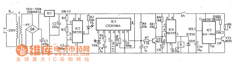
The schematic for an infrared burglar alarm circuit is depicted in Figure 1. The infrared transmitter operates as a multivibrator with an oscillation frequency of 40 kHz, utilizing the NE555 integrated circuit (IC2), along with resistors R1 and R2...
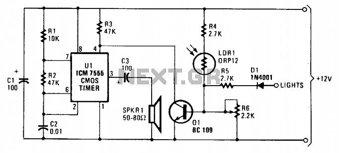
As dusk begins to fall, the sensor, which is a cadmium-sulfide light-dependent resistor (LDR), activates a small horn to provide an audible reminder to turn on the lights. The circuit can be turned off by simply switching on the...
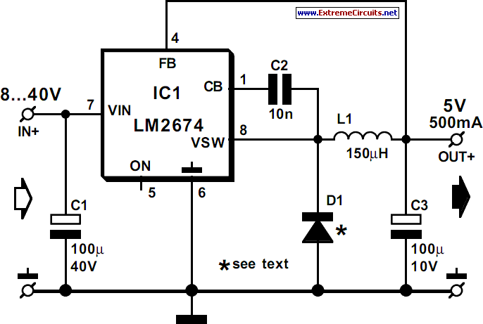
National Semiconductor has been designing and manufacturing integrated circuits (ICs) for switch-mode power supplies for many years. The application of these devices is typically straightforward, supported by comprehensive documentation. A common example of a switch-mode power supply is based...
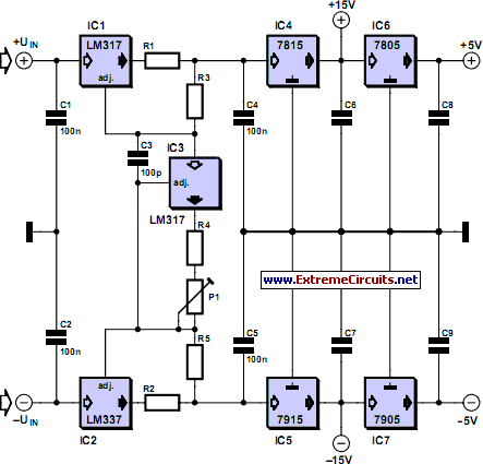
This current-limiting circuit, illustrated in this example as part of a small bench power supply, could theoretically be utilized alongside any dual-rail current source. The section of the circuit to the left of the diagram restricts the input current...
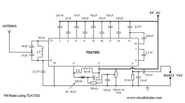
A simple FM radio circuit with a diagram and schematic using the IC TDA 7000. This low-cost single-chip FM radio circuit design is easy to assemble and is suitable for creating a portable FM radio. The FM radio circuit utilizing...
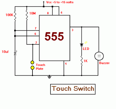
This electronic circuit utilizes a 555 timer as the foundation for a touch switch. When the plate is touched, the 555 timer is activated, causing the output on pin 3 to go high, which turns on the LED and...