
Touch Switch Circuit with explnation

The described electronic circuit is a touch-activated switch based on the 555 timer IC, a versatile component widely used in timer, delay, pulse generation, and oscillator applications. The 555 timer operates in monostable mode in this configuration, where it generates a single output pulse when triggered.
In this circuit, the touch plate acts as a trigger mechanism. When the plate is touched, it sends a signal to pin 2 of the 555 timer, which is configured to respond to a negative-going edge. The 10M resistor connected to pin 2 ensures high sensitivity, allowing the circuit to detect even slight touches. This high-resistance value minimizes the current draw and enhances the responsiveness of the switch.
The timing component of the circuit is determined by the resistor and capacitor connected to pins 6 and 7. The time period for which the output remains high (i.e., the duration that the LED and buzzer are activated) can be calculated using the formula:
\[ T = 1.1 \times R \times C \]
where \( T \) is the time in seconds, \( R \) is the resistance in ohms, and \( C \) is the capacitance in farads. By selecting appropriate values for the resistor and capacitor, the user can customize the duration of the output pulse to suit specific requirements.
The output on pin 3 of the 555 timer is capable of driving an LED directly, providing visual feedback when activated. Additionally, the output can be connected to a buzzer, which produces an audible signal, enhancing the functionality of the touch switch.
Overall, this circuit exemplifies the practical application of the 555 timer in creating a simple yet effective touch-sensitive switch, suitable for various electronic projects and educational purposes.This electronic circuit uses a 555 timer as the bases of the touch switch. You can learn more about 555 timers in the Learning section on my site. When the plate is touched the 555 timer is triggered and the output on pin 3 goes high turning on the LED and the buzzer for a certain period of time. The time that the LED and the buzzer is on is based on the values of the capacitor and resistor connected to pin 6 & 7. The 10M resistor on pin 2 causes the the circuit to be very sensitive to the touch. Disclaimer All files are found using legitimate search engine techniques. This site does not and will not condone hacking into sites to create the links it list. We will and do assume that all links found on the search engines we use are obtained in a legal manner and the webmasters are aware of the links listed on the search engines. If you find a URL that belongs to you, and you did not realize that it was "open to the public", please use the report button to notify the blogmaster of your request to remove it or it will remove within 24 hours.
This is not an invitation for webblog haters to spam with requests to remove content they feel that is objectionable and or unacceptable. Proof of URL ownership is required. NOTICE: This Blog Has Already Been Reviewed And Accepted By Blogger. com 🔗 External reference
Related Circuits
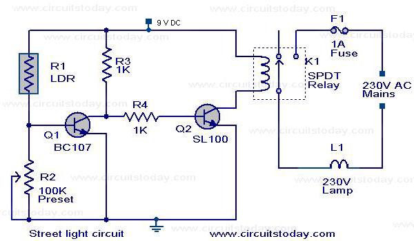
A street light that automatically switches ON when night falls and turns OFF when the sun rises. The circuit uses an LDR to sense the light. The automatic street light circuit functions by utilizing a Light Dependent Resistor (LDR) as...

A fluorescent starter bimetal can be utilized as a temperature sensing element for thermostatic control. This component consists of a double metal sheet designed for temperature sensing, resulting in a simple circuit that is easy to manufacture, although it...

A compilation of dial phone numbers, including 15 commonly used libraries and the dialed number, is stored in standard CMOS RAM. A single-button keypad facilitates the input of a phone number, which can be dialed directly or stored in...

The FM modulator is constructed using a Motorola MC1648P oscillator. Two varactors, the Motorola MV-209, are employed to frequency modulate the oscillator. A 5000-ohm potentiometer is utilized to bias the varactors for optimal linearity. The output frequency, which is...
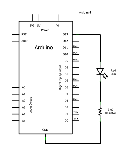
Arduino consists of two main components: the hardware (the Arduino board) and the software (the IDE). The advantage of using Arduino is that circuits can be built and their behavior modified by altering the code instead of changing the...

The primary objective is to present the circuit diagram and describe the software utilized. A UDP application is employed to transmit commands to the microcontroller, which subsequently activates or deactivates the relay. It is anticipated that TCP implementation could...