
Electronic Selector for 10 sources with Display-Relay Drive circuit

The circuit operates by allowing the user to select between multiple power sources or signal inputs through a mechanical rotating switch (S1). This switch is connected to a series of relays (RL1 to RL10), which are electronically driven to switch the selected source to the output. Each relay corresponds to a specific input or source, enabling the circuit to handle various operational requirements.
The electronic drive for the relays is typically implemented using a microcontroller or a dedicated relay driver IC, which receives input from the rotating switch. This design ensures that the selected relay is activated while others remain deactivated, preventing cross-talk between sources. The relays are chosen based on their switching capacity to handle the required voltage and current levels of the signals being managed.
To provide visual feedback to the user, an optical indication is achieved through the display (DSP1). This display can be an LED array, LCD, or other types of visual indicators that illuminate or change state to reflect the current selection made via the switch. The display is updated in real-time as the switch is rotated, ensuring the user is always aware of which source is currently active.
The overall design emphasizes reliability and user-friendliness, making it suitable for applications where multiple sources need to be managed efficiently, such as in audio systems, power distribution systems, or laboratory setups. Proper consideration should be given to the layout of the circuit to minimize noise and interference, particularly in sensitive applications. Additionally, the selection mechanism should be robust to ensure longevity and consistent performance over time.This is a circuit for alternative sources selection. It combines mechanical selection using a rotating switch S1, the electronic drive of the relays RL 1-10 and also the optical indication of the selection by the Display DSP1.. 🔗 External reference
Related Circuits
This circuit is a simple 12V DC to 220V AC inverter that produces an AC output at line frequency, specifically 220V AC, or other voltages by selecting transformer T1. The 555 integrated circuit (IC) is configured as a low-frequency...
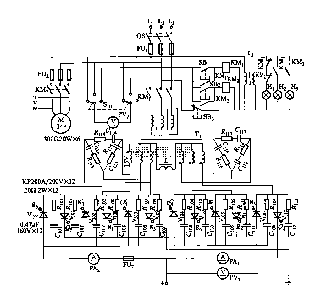
FGDF-3 is a three-phase low-temperature iron plating main circuit, while the KGDF-3 represents a low-temperature iron plating power supply device that includes characteristics of a single-phase low-temperature iron plating power supply. This device utilizes a three-phase power grid to...
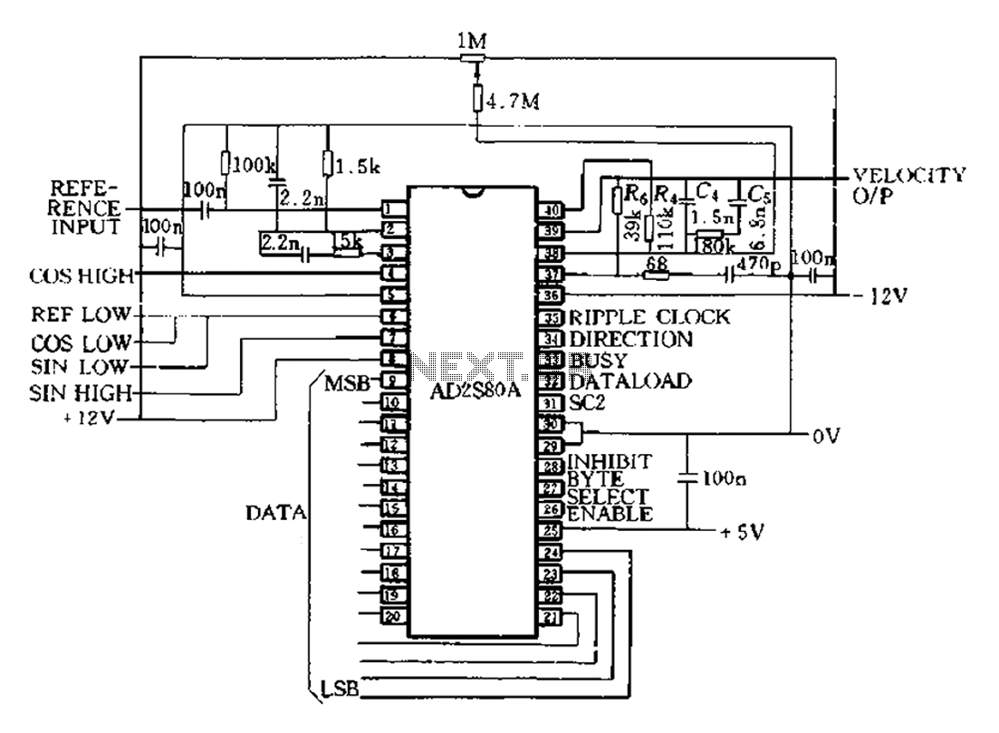
The AD2S80A represents a typical application circuit, detailing specific peripheral connectivity and device parameters. It is configured for a 12-bit resolution (SCl-0, Sc2 1) to select a reference frequency of 5 kHz. The bandwidth is 520 Hz, with a...

An AC-DC power supply without a power switching circuit is typically utilized for lighting load circuits. Once the power grid is restored, the standby power supply automatically switches on. An automatic switching circuit using a transistor is implemented, with...
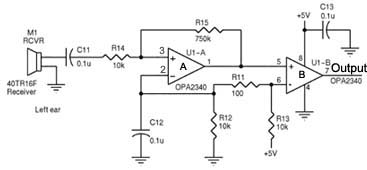
Assistance is required regarding the circuits provided below. The focus is on an ultrasonic receiver circuit that utilizes two ultrasonic components. The ultrasonic receiver circuit is designed to detect ultrasonic waves, typically in the frequency range of 20 kHz to...

The design of the digital logic probe centers around a pair of complementary bipolar transistors, which, in this application, are used as electronic switches. The digital logic probe is a diagnostic tool utilized for testing and analyzing digital circuits. The...