
12VDC to 220VAC Inverter Circuit Using IC 555

This inverter circuit operates by converting a low voltage DC input into a high voltage AC output suitable for various applications. The 555 timer IC is pivotal in generating a square wave signal that controls the switching of the transistors, which act as amplifiers to drive the transformer. The frequency potentiometer R4 allows for fine-tuning of the output frequency, accommodating variations in application requirements, particularly for devices that may be sensitive to frequency fluctuations.
Transformer T1 plays a crucial role in stepping up the voltage from the low DC level to the desired AC output level. The choice of transformer is essential, as it must be rated for the appropriate voltage and current to handle the load. The filtering components, capacitor C4 and inductor L1, are designed to smooth the output waveform, minimizing harmonic distortion and ensuring that the output closely resembles a sine wave, which is critical for the operation of many AC devices.
The selection of transistors Q1 and Q2 is also significant as they need to handle the power levels involved without overheating or failing. The recommended replacement parts provide alternatives that can be used if the original components are unavailable, ensuring the circuit can be maintained or repaired easily.
When designing or modifying this inverter circuit, careful consideration must be given to the input voltage range, as this will affect the performance and efficiency of the inverter. The 2700µF capacitor serves as a reservoir for the DC input, and its voltage rating must be selected based on the expected maximum input voltage to prevent failure. Overall, this inverter circuit represents a versatile solution for converting low voltage DC power into usable high voltage AC power, suitable for a wide range of applications.This is a simple 12VDC to 220AC inverter circuit that can be used produces an AC output at line frequency and 220AC or different voltage by selecting transformer T1. The 555 IC is configured as a low-frequency oscillator, tunable over the frequency range of 50 to 60 Hz by Frequency potentiometer R4.
The 555 feeds its output (amplified by Q1 and Q2 ) to the input of transformer T1, a reverse-connected filament transformer with the necessary step-up turns ratio. Capacitor C4 and coil L1 filter the input to T1, assuring that it is effectively a sine wave. Adjust the value of T1 to your voltage. The output ( in watts) is up to you by selecting different components. Input voltage is anywhere from +5V to +15Volt DC, adjust the 2700uF cap`s working voltage accordingly.
Replacement types for Q1 are: TIP41B, TIP41C, NTE196, ECG196, etc. Replacement types for Q2 are: TIP42B, TIP42C, NTE197, ECG197, etc. 🔗 External reference
Related Circuits
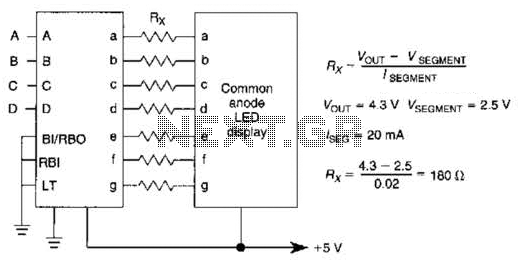
An IC1, such as the 7447, drives a common anode 7-segment LED display. The current-limiting resistor R must restrict the segment current to the rated value at the maximum supply voltage. A sample calculation is provided. The 7447 integrated circuit...
The circuit features an adjustable prestage utilizing the AF279 transistor, while the natural oscillation mixer stage employs the AF280 transistor. The power circuit is mounted on a board with copper coating. The main coil specifications are as follows: L1,...
Approximately one watt RMS appears to be a suitable output level, which is also the maximum power that a basic amplifier powered by 12V can deliver to an 8 Ohm speaker. A very low saturation amplifier may reach up...

A high-power and efficient 100W power amplifier electronic project can be designed using the STK404 audio power amplifier hybrid ICs. These ICs consist of optimally designed discrete component power amplifier circuits that have been miniaturized using SANYO's unique insulated...
The figure illustrates a schematic for an oscillator amplitude-control servo system. The circuit establishes a closed-loop system that provides a fixed and adjustable peak-to-peak amplitude AC signal centered around 0 V. A 1 kHz sine wave, designated as AC_INPUT,...
An FM transmitter, commonly referred to as an FM transmitter, utilizes two transistors, specifically the 2N2222 model. When in operation, this FM transmitter requires a 9-volt battery for power and operates with an antenna that is less than 12...