
Electronic ship siren

The circuit functions as a tone generator, utilizing a multivibrator configuration formed by transistors Q1 and Q2, which operate in a feedback loop to produce oscillations. The frequency of oscillation, and thus the tone produced by the siren, is determined by the values of capacitors C1 and C2, which create a timing interval that governs the charge and discharge cycles of the capacitors. The output from the collector of Q2 is a square wave signal that can be utilized to drive a speaker directly or through an output transformer, depending on the speaker's impedance.
For speakers with an impedance lower than the specified range, the output transformer serves to match the impedance, ensuring efficient power transfer and preventing damage to the circuit components. The low-power output stage Q3 amplifies the signal from the multivibrator, providing sufficient power to drive the speaker without excessive energy consumption.
The electrolytic capacitor (1 µF) connected to the collector of Q2 acts as a coupling capacitor, allowing AC signals to pass while blocking DC components, thus protecting the amplifier input from any potential DC bias. The series resistor (12 kΩ) serves to limit the current flowing into the amplifier, ensuring that the input stage operates within its specified limits and preventing distortion of the signal.
Overall, this circuit design is suitable for applications requiring sound generation, such as alarms or signaling devices, with the flexibility to accommodate different speaker types through the use of an output transformer. The minimal quiescent current indicates that the circuit is energy efficient, making it ideal for battery-powered applications.The circuit consists of a multivibrator (Ql & Q2), and a low power output stage Q3. The speaker should have an impedance in the region of 40 to 80 ohms. To use a low impedance speaker, connect an output transformer from the emitter of Q3 to ground. Cl and C2 determine the pitch of the siren and the values specified will provide a tone of about 300 Hz. Quiescent current is negligible. The output at the collector of Q2 can also be fed into an amplifier input via a 1 µf electrolytic, in series with a 12 k resistor.
Related Circuits
Modern ICON electronic engine controls from BRP The ICON electronic engine control system developed by Bombardier Recreational Products (BRP) represents a significant advancement in marine technology. This system integrates sophisticated electronic controls to enhance the performance and reliability of marine...
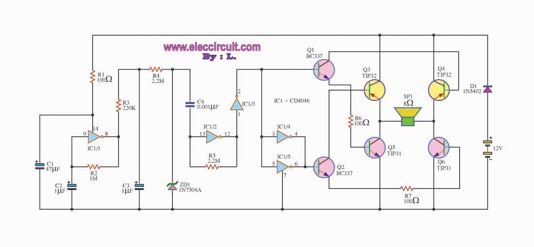
This is a simple siren sound generator with high power output and significant noise levels. The circuit utilizes digital integrated circuits (ICs), specifically the CD4046, in an inverter configuration along with four transistors to increase the current output to...
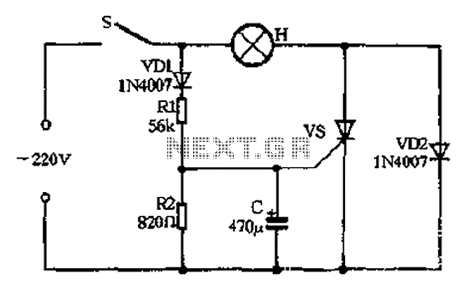
The circuit operates as follows: When the momentary switch S is activated, the voltage across the capacitor cannot change instantly, resulting in zero voltage across the SCR, which does not trigger. Consequently, the voltage cut-off occurs. In this scenario,...
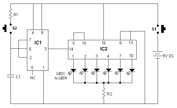
It is advisable to enclose this circuit in a box and label each LED with numbers from 1 to 6. When switch S1 is momentarily pressed, one of the six LEDs will illuminate, with the number corresponding to the...
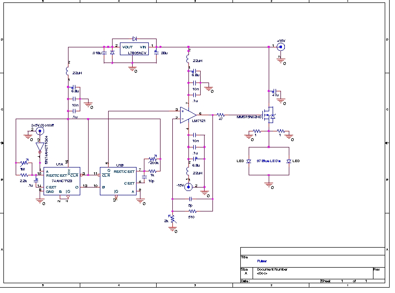
A Prototype Sample and Hold Circuit - The original concept for the veto front-end amplifiers was to continuously sample the input pulse height and maintain the pulse height for any pulses exceeding a low voltage threshold (approximately 10 mV)....
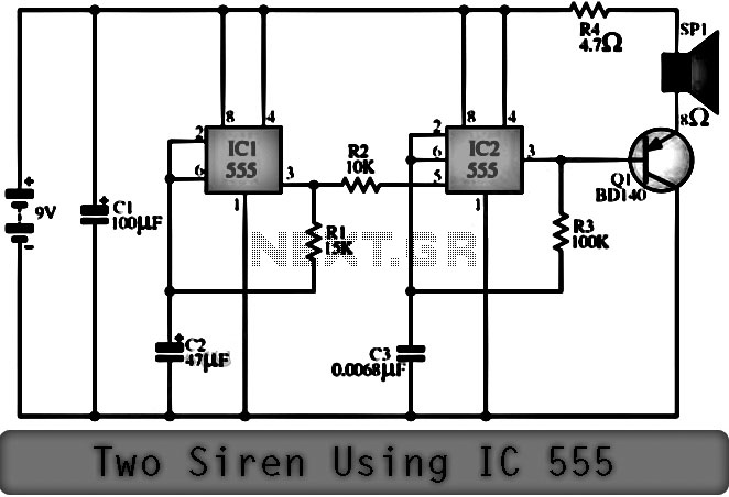
The function of the Two Siren Sound Circuit utilizing IC 555 is divided into three parts: low frequency production, manufacturing of a shrill frequency, and low frequency output. The low frequency is generated by IC1, which is connected to...