
Electronic signs sound and light control

The automatic electronic circuit integrates several essential components to achieve its functionality. The voice circuit is responsible for processing audio signals, which may involve converting sound waves into electrical signals and vice versa. This component typically includes a microphone for sound input and a speaker for sound output, along with necessary amplification stages to ensure adequate signal levels.
The oscillation circuit generates a specific frequency signal that is crucial for the operation of the entire system. This circuit may utilize various components such as resistors, capacitors, and inductors to create oscillations at the desired frequency. The generated signal can serve multiple purposes, including timing functions or modulation of the voice circuit.
The driving part of the display circuit is responsible for controlling visual indicators, which may include LEDs or LCDs. This section interprets the output from the voice and oscillation circuits and translates it into a format suitable for display. It may consist of driver transistors or integrated circuits that manage the power requirements of the display elements, ensuring they operate efficiently and effectively.
Together, these components form a cohesive system capable of responding to audio inputs and providing visual feedback, making it suitable for various applications in automation and user interface design. The circuit's design emphasizes reliability and responsiveness, ensuring that it meets the demands of modern electronic applications. Automatic electronic circuit shown in Figure signs, it is mainly by voice circuit, an oscillation circuit and a driving part of the display circuit.
Related Circuits
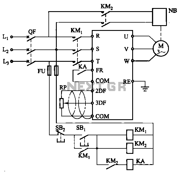
Electromagnetic brake motors consist of a motor and an electromagnetic brake, forming a standard assembly. The circuit diagram is provided. In this configuration, FR represents the forward run and stop command terminal, while the intermediate relay KA is employed...
I found some similar circuits but aren't good enough for me. Some circuits measure the water's resistance to determine the level. That is dangerous for drinking water (contamination) or explosive liquids because electricity is in contact with water. The...
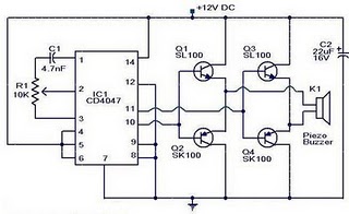
The circuit operates on the principle that insects, such as mosquitoes, can be repelled using sound frequencies in the ultrasonic range (above 20 kHz). It utilizes a Phase-Locked Loop (PLL) integrated circuit, specifically the CMOS 4047, configured as an...
This document outlines modifications made to the RIG RX-2 receiver, enabling remote control via a computer using an RS-232 serial interface. The modifications consist of two components: additional hardware and a new firmware program for the PIC16C84 microcontroller. In...
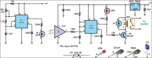
The IR detector (IC3) controls an LM 7555 CMOS timer (IC2) operating in monostable mode. When the beam is interrupted, IC2 is triggered, and its pin 3 output goes high for approximately half a second. This action extinguishes LED1...
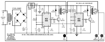
This is a simple traffic light controller that can be used to teach children the basics of traffic light rules. The circuit employs commonly available electronic components and consists of rectifier diodes (1N4001), a 5V regulator (7805), two timer...