
Electromagnetic brake motor frequency control circuit

The electromagnetic brake motor circuit operates by integrating a standard motor with an electromagnetic brake system, which ensures that the motor can stop quickly and hold its position when not in operation. The circuit involves several key components, including the motor, the electromagnetic brake, the forward run (FR) command terminal, and an intermediate relay (KA).
The forward run command terminal (FR) serves as the input for initiating the motor's operation. When a signal is applied to this terminal, it activates the intermediate relay (KA), which in turn energizes the motor. The relay functions as a switch that can handle higher currents than the command terminal, ensuring safe and efficient operation.
The electromagnetic brake is designed to engage when the power to the motor is cut, providing immediate braking action. This feature is particularly advantageous in applications requiring rapid stops or where load holding is critical. The brake is typically powered by the same circuit and is released when the motor is energized, allowing for smooth operation during forward runs.
The circuit may also include additional safety features such as overload protection devices and limit switches, which can prevent the motor from operating under unsafe conditions. These components are essential for maintaining the integrity of the system and ensuring reliable performance over time.
Overall, the integration of the electromagnetic brake with the motor and the use of an intermediate relay for control creates a robust system capable of handling various operational demands in industrial and commercial applications.Electromagnetic brake motors from the motor and electromagnetic brake NB ordinary composition. Circuit is shown. Figure, FR is the forward run and stop command terminal; intermediate relay KA is used to control the motor started.
Related Circuits
Men often appreciate the convenience of television remote controls, which can sometimes frustrate their female partners. They tend to switch channels frequently, wanting to ensure they do not miss anything while a specific program is on. With the remote...
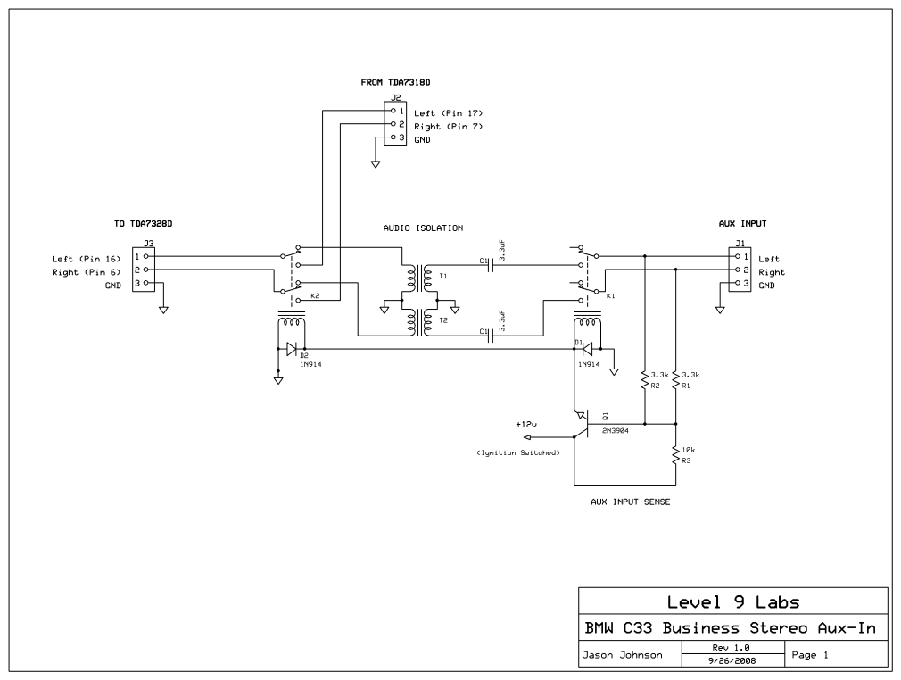
The layout of the PC board led to the decision to insert a stereo 3mm canceling type jack (5 pin) at the volume control chip inputs, which was mounted on the front panel. A suitable jack was not available...
This circuit was developed in response to requests from website visitors for a timer that can emit a beep after intervals of one, two, three minutes, and so forth, for jogging purposes. As depicted in the circuit diagram, SW1...
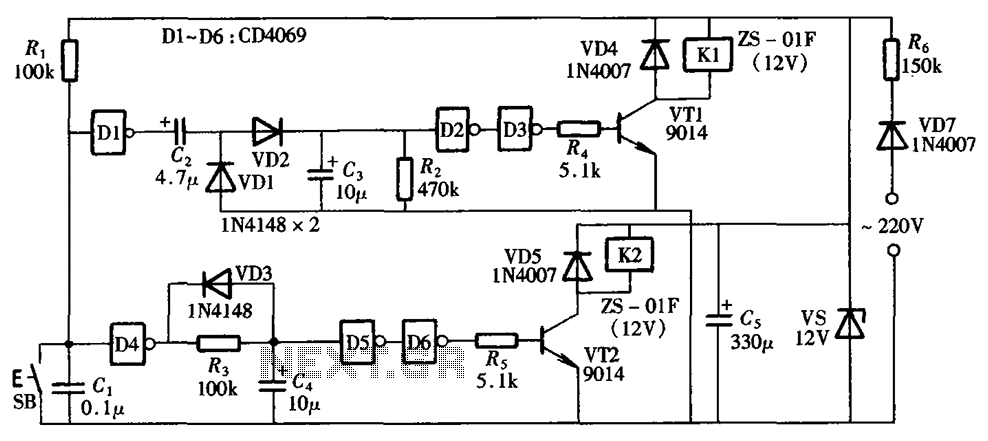
A one-button control switch is designed to control two relays, each of which can switch the load power on and off as needed. The circuit primarily consists of a hex inverter CD4049 and two self-locking DC relays. The circuit utilizes...
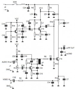
This is the circuit diagram of an audio/video modulator. The circuit converts audio and video signals into a UHF TV signal. It is designed to connect a video signal originating from a camera or other video source to a...
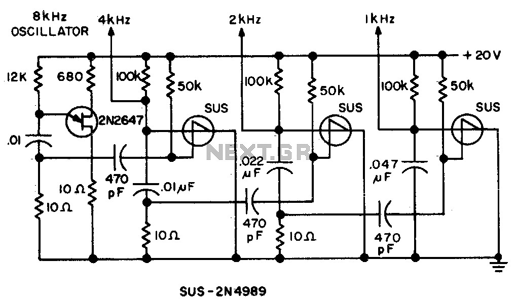
Spikes in the center of a sawtooth wave are eliminated in this circuit by triggering at specific intervals. This circuit is designed to mitigate unwanted spikes that occur in the center of a sawtooth waveform. The sawtooth wave, characterized by...