
Electronics Projects: Simple 12 Volt Day Night Switch

An LDR (Light Dependent Resistor) connected to the input of the NAND gate is used to detect variations in light levels. The LDR is a resistor that changes its resistance value based on the intensity of light falling on it. In the absence of light, or when it is dark, the LDR presents an infinite resistance, causing the input of the NAND gate to be at a logic high due to the voltage from a variable resistor (VR1). Consequently, the output of the NAND gate is logic low, activating the relay through the transistor (T1) and switching on the connected lights (load). As ambient light increases, the resistance of the LDR decreases. When the resistance drops below a certain threshold, the input of the NAND gate becomes logic low, resulting in a high output that turns off the transistor, the relay, and the lights.
The entire circuit for this 12-volt day-night switch can be constructed on a small piece of general-purpose PCB, and the assembly, along with the transformer, can be housed in an aesthetically pleasing ABS plastic enclosure. The LDR should be positioned externally so that it can accurately sense ambient daylight. It is crucial to ensure that no stray light or the light being controlled can reach the LDR, as this could cause false switching and oscillation. The optimal installation position for the unit is at a height above the lights it controls. This automatic night light system can also be effectively used to manage building porch lights, neon signs, large advertising displays, gallery lights, and automatic decorative interior lights for homes. This simple, cost-effective circuit not only alleviates the burden of manually switching lights on and off but also promotes economical usage of lighting resources.At times it`s really very annoying to see the street lights kept switched ON even during broad day light. The present circuit of an automatic night light can very effectively put an end to this problem. Read here how to build it. We all know how important it has become tosave electricityin today`s circumstance where it is getting difficult to fulf
ill the power requirements for our cities. Today everybody along with the politicians and the official authorities are busy putting forth their own opinions regarding the issue. But ironically at times we find the street lights kept switched on even during broad daylight, and this clearly shows how irresponsible these men can be.
So instead of depending on these officials, why not take some help fromelectronicsand find a solution to get the work done automatically A simple circuit of an automatic night light described in this article can very accurately switch ON a load (street lights for example) when darkness falls and switch it OFF when dawn breaks. A single NAND gate, a PNP transistor and few other passive components are the only things needed to construct this useful gadget.
The circuit description can be understood from the following explanation: An LDR (Light Dependent Resistor) which is also connected at the input of N1 is used to sense a difference in light levels. A LDR is in fact a resistor which changes its value with a change in the intensity of light falling on it.
In the absence of light or when its dark, the LDR offers an infinite resistance and thus the input of N1 is kept at logic high due to the voltage received through VR1. This means that at this instant the output of N1 is logic low, the relay is activated through T1 and the lights (load) connected to the relay contacts are switched ON.
With an increase in the ambient light the resistance of the LDR will gradually fall and after a certain level the input of N1 will become logic low. Immediately its output will go high switching OFF the transistor, the relay and the lights. The entire circuit of this 12 volt day night switch can be built over a small piece of general PCB and the whole assembly along with the transformer may be housed inside a good looking ABS plastic enclosure.
Only the LDR has to be fixed over the box so that it can sense the ambient daylight. Take due care to position the LDR in such way that no other stray light or the light which it`s controlling is able to be incident on it, or else it may produce false switching and may start oscillating. The best position would be to install the unit at a point much higher than the lights which are controlled by it.
This automatic night light system may also be appropriately used to control building porch lights, neon signs, large advertising displays, gallery lights and also as automatic house interior decorative lights. Thus this simple inexpensive circuit should not only be able to relieve you from the headache of timely switching the particular lights but also will result in quite an economical way of using them.
🔗 External reference
Related Circuits
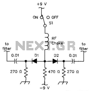
D1 and D2 can be IN914B or HP2800-series diodes (for UHF). The loss is over 60 dB in the off state and less than 3 dB at 3.5 to 30 MHz (using common IN914B diodes). The circuit utilizes D1 and...
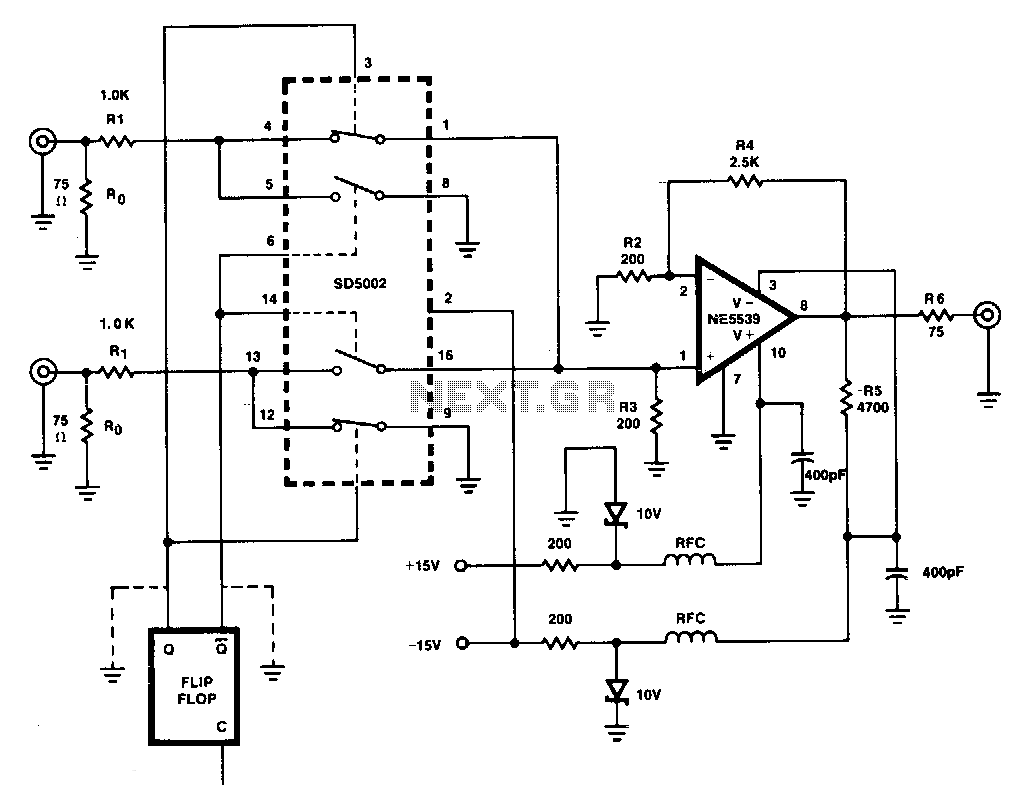
This figure illustrates a one-of-two switch featuring a summing amplifier. The video source's line can be terminated either externally or internally to switch RO. With this termination resistor, a load change of less than 10 ohms will be perceived...
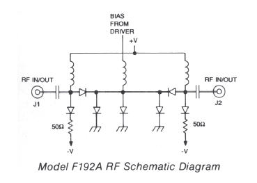
High-speed frequency range of 0.2 to 18 GHz with 80 dB isolation. Features non-reflective performance, low Voltage Standing Wave Ratio (VSWR), and minimal insertion loss. Compact and lightweight design. This electronic component is designed to operate efficiently across a broad...

One of the drawbacks of a three-pin voltage regulator is that the input voltage needs to be 2.5 to 3 V higher than the output voltage. This makes these integrated regulators unsuitable for battery power supplies. For instance, if...
A simple water level sensor or liquid level detector for measuring or detecting a required level of water, liquid, or fluid in a tank, pool, well, aquarium, washing machine, etc. The water level sensor is an essential device utilized for...
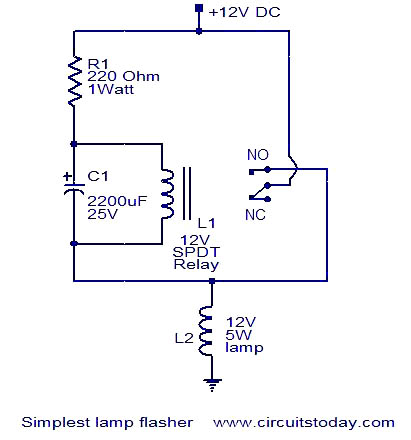
This is a simple lamp flasher circuit that utilizes only three components (a capacitor, a relay, and a resistor) in addition to the lamp. The operation of the circuit is straightforward. When power is turned on, the capacitor C1...