
Simplest lamp flasher circuit

The lamp flasher circuit operates based on the principles of capacitance and relay switching. The capacitor (C1) plays a crucial role in determining the timing of the flashing effect. The resistor limits the charging current to the capacitor, thereby controlling the rate at which the capacitor charges. The value of the resistor (R) and the capacitor (C1) can be selected to adjust the time duration for which the lamp remains lit and the time duration for which it is off, thus altering the flash rate.
When the circuit is powered, the capacitor begins to charge through the resistor. The charging time is defined by the RC time constant, which is calculated as τ = R × C. This time constant dictates how quickly the voltage across the capacitor rises. Once the voltage across C1 reaches the relay's activation threshold, the relay coil is energized, closing the normally open contacts and allowing current to flow to the lamp.
As the capacitor continues to charge, the relay remains activated, and the lamp stays illuminated. Eventually, the capacitor reaches its maximum charge and begins to discharge. The discharge occurs through the load or any path provided in the circuit. As the voltage across the capacitor drops below the relay's release voltage, the relay deactivates, opening the circuit and turning off the lamp.
The cycle repeats as long as power is supplied to the circuit, creating a flashing effect. The frequency of the flashing can be adjusted by changing the values of the resistor and capacitor, allowing for customization based on the desired application. This simple yet effective design is commonly used in decorative lighting, signaling devices, and various low-power applications where a visual alert is needed.This is a very simple lamp flasher circuit that uses only three components (a capacitor, relay and one resistor) other than the lamp. The working of the circuit is very straight forward. When the power is switched ON the capacitor C1 charges through the resistor. When the voltage across the capacitor is sufficient, the relay switches ON and the la mp connected via the normally open contact of the relay glows. The relay remains energized until the capacitor discharges and then the lamp extinguishes. The charging and discharging cycle of the capacitor gives a flashing effect to the lamp. 🔗 External reference
Related Circuits
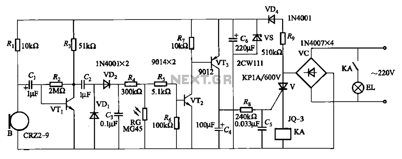
A resistor R8, capacitors Cd, and a thyristor V AC switch form a delay circuit. The lamp's lighting delay time is determined by the resistor Rs and capacitor C4, with a delay of approximately 40 seconds as indicated in...
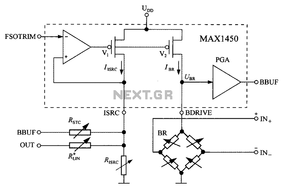
The circuit diagram for the bridge integrated pressure signal conditioner MAX1450 is composed of various components. The MAX1450 is a high-performance integrated circuit designed for signal conditioning in pressure sensing applications. It is particularly suited for use with resistive bridge...

The low-cost and compact circuit presented here serves as a highly power-saving flashing LED indicator. While most LEDs typically fail to operate below 2 volts, with a forward voltage of at least 1.6 volts, this flasher can function using...
All resistors have a tolerance of 5 or 10 percent and are rated for 1/4 watt. All capacitors have a tolerance of 10 percent and are rated for 35 volts or higher. This circuit effectively amplifies the output of...
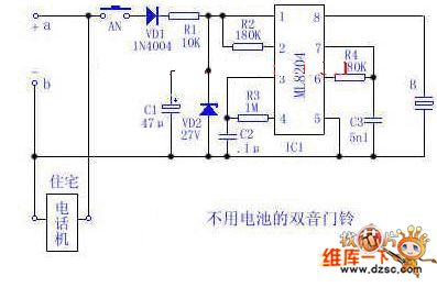
Utilize the 48V (60V) DC feedback electric current supplied by the phone feedback line as the operational energy source for the electronic doorbell, which is highly economical and practical. This document introduces a two-tone doorbell circuit that operates without...
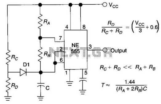
Using Rl, R7, and D1 to preset CI to one third of the supply voltage. This circuit avoids a longer first cycle period than subsequent cycles. The circuit described involves the use of resistors Rl and R7 along with diode...