
ELF MONITOR
The capacitor testing instrument operates on the principle of applying a known voltage to the capacitor under test and monitoring the response. The circuit typically consists of a voltage source, a microcontroller or comparator for signal processing, and display elements for output indication.
The testing process begins by charging the capacitor with a specific voltage. The instrument measures the time it takes for the capacitor to charge to a predetermined threshold voltage. This time is then compared against known values to determine the capacitor's condition. If the capacitor charges too quickly, it may indicate a short circuit; if it does not charge at all, this could signify an open circuit.
Additional features may include a digital display to show capacitance values, a buzzer for audible alerts when a defective capacitor is detected, and a range switch to accommodate different capacitance levels. The design may also incorporate safety features such as discharge circuits to prevent damage to the components or accidental shocks.
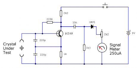
The circuit schematic would illustrate the connections between the voltage source, the test capacitor, the microcontroller, and the output indicators. Key components might include resistors to limit current, capacitors for filtering, and diodes for protection against reverse polarity. Overall, this instrument is an essential tool in electronic manufacturing and repair, ensuring that only functional capacitors are used in circuit assemblies.Capacitor instrument is not to be used to measure the capacity of the capacitor but for identifing good or bad and short circuit or open circuit, then it provides a reliable quality assurance for the production of circuit to reduce the circuit making unnecessary trouble. The circuit is shown as figure. The instrument can identify 1pF ~ 1 F capaci tors. (View) 🔗 External reference
Related Circuits
Figure A illustrates the circuit of a direct-trigger timing light. The trigger voltage is obtained from the vehicle's ignition circuit via a direct connection to a spark plug. Figure B depicts a circuit utilizing an inductive pickup. A trigger...
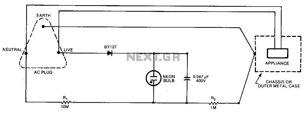
A continuous glow signifies that everything is normal; a blinking or extinguished neon bulb indicates a broken earth or ground connection, or interchanged neutral and live wires. In electronic circuits, a neon bulb is often used as an indicator light...
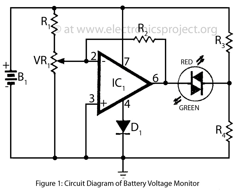
Battery voltage monitor is utilized to indicate the voltage level of a 12-volt battery circuit, specifically in a verified electronics project circuit. The battery voltage monitor circuit is designed to provide a visual representation of the voltage level of a 12-volt...
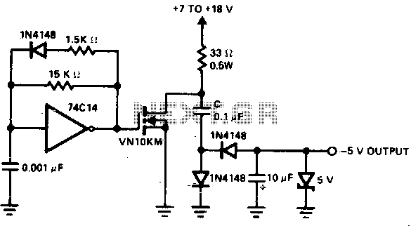
A low-power converter designed to derive a higher voltage from a main system rail in an on-board application. The operating frequency with the transformer depicted is 250 kHz. Z1 functions as a dissipative voltage regulator for the output and...
The circuit monitors PC keyboard activity through a five-pin DIN connector J1. When a key is pressed, the keyboard transmits a series of negative-going pulses on pin 2. In conjunction with Q1 and C3, the operational amplifier operates as...
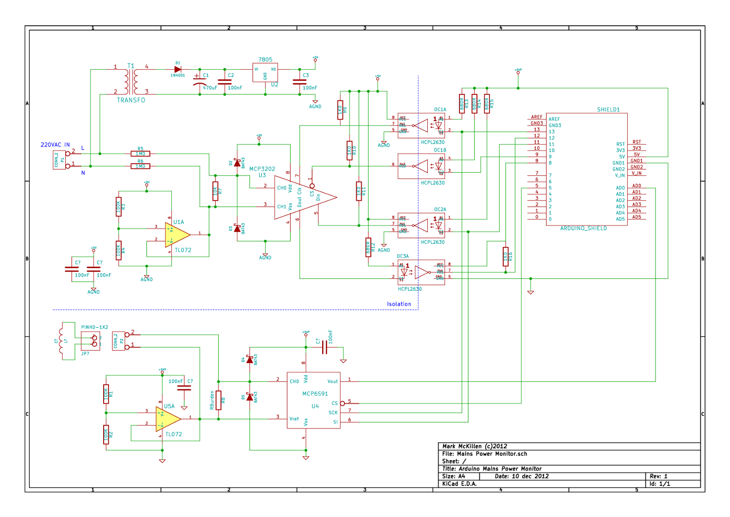
A mains (220-240VAC) power monitoring circuit has been sought for interfacing with an Arduino. While the OpenEnergyMonitor solution employs a transformer for isolation and measurement of mains voltage, it has been noted that the transformer does not couple effectively...