
Emergency Light With Battery Charger

The Emergency Light with Battery Charger Circuit is designed to provide illumination during power outages while simultaneously ensuring that the battery remains charged when mains power is available. The circuit typically consists of a light-emitting diode (LED) or a compact fluorescent lamp (CFL) as the light source, a rechargeable battery, a charging circuit, and a control mechanism that automatically switches the light on when the mains power fails.
The primary components of the circuit include:
1. **Light Source**: An LED or CFL is utilized for its energy efficiency and long lifespan. The choice of light source will depend on the intended brightness and power consumption.
2. **Rechargeable Battery**: A sealed lead-acid (SLA) battery or lithium-ion battery is commonly used to store energy. The battery capacity should be selected based on the desired backup time and the power rating of the light source.
3. **Charging Circuit**: This circuit is responsible for charging the battery when mains power is available. It typically includes a transformer to step down the voltage, a rectifier to convert AC to DC, and a voltage regulator to ensure the battery is charged at the appropriate voltage level.
4. **Control Mechanism**: A relay or a transistor can be employed to switch the light on automatically when the mains power is lost. This mechanism detects the absence of mains voltage and activates the light source using the stored energy from the battery.
5. **Indicator LED**: An additional LED may be included to indicate the status of the circuit, such as whether the battery is charging or if the system is in emergency mode.
The circuit is designed to be compact and efficient, ensuring that the emergency light operates seamlessly during power interruptions, providing essential lighting for safety and convenience. Proper thermal management and component ratings are crucial to ensure reliability and longevity of the circuit during operation.The following circuit shows about Emergency Light With Battery Charger Circuit Diagram. Features:automatic switching-on of the light on mains .. 🔗 External reference
Related Circuits
There are many measurement systems that would be more suitable if a logarithmic scale is used, especially when attempting to mimic human sensory responses. Most... Logarithmic scales are particularly effective in representing a wide range of values in a compact...
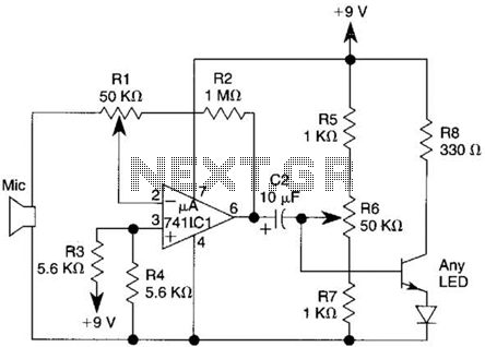
This transmitter utilizes a 741 operational amplifier as a high-gain audio amplifier, which is activated by a microphone. The output of the 741 is connected to Q1, functioning as the driver for an LED. Potentiometer R1 serves as the...
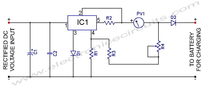
L200 12V Constant Voltage Battery Charger Circuit. This battery charger is based on the L200 regulator IC. The L200 is a five-pin adjustable voltage regulator. The L200 constant voltage battery charger circuit is designed to provide a stable 12V output...
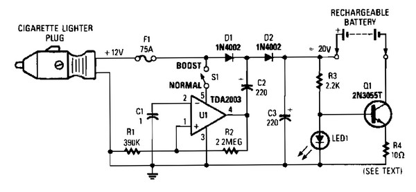
V1 creates a square wave oscillator, while D1 and D2 couple this square wave to a 12-V battery, raising the voltage to over 20 VDC. If this elevated voltage is not required, S1 can remain open. Q1 functions as...
This device is a simple timer that keeps the headlights of a vehicle on for approximately 1 minute and 30 seconds, allowing for illumination when accessing dark areas without the need to return to switch off the lights. Pressing...
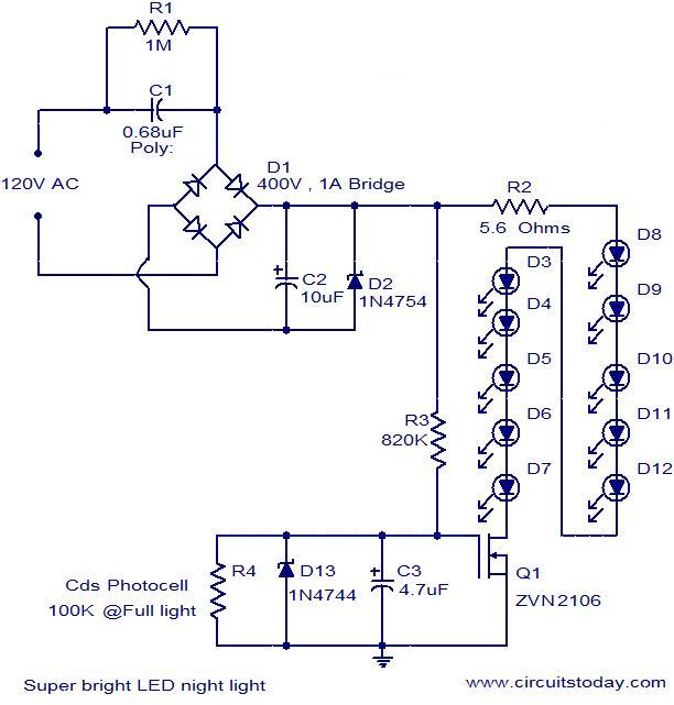
The circuit diagram illustrates a super bright LED night lamp that operates from the mains supply. A bridge rectifier (D1) is employed to convert the AC mains voltage into DC. The combination of capacitor (C1) and resistor (R1) forms...