
12vdc mobile battery charger

The circuit consists of several key components that work together to form an efficient mobile battery charging system. The square wave oscillator (V1) generates a periodic square wave signal, which is essential for driving the subsequent components. The output from V1 is fed into diodes D1 and D2, which rectify the AC component of the square wave, allowing for the conversion of the 12-V battery voltage into a higher DC voltage exceeding 20 VDC. This elevated voltage is particularly useful for charging applications where higher voltages are necessary.
Switch S1 provides flexibility in the design; when not needed, it can be left open, effectively bypassing the circuit that elevates the voltage. This feature allows the circuit to operate under different conditions depending on the requirements of the battery being charged.
Transistor Q1 is employed as a current regulator, a critical component that ensures the charging current is maintained at a safe level for rechargeable batteries. This regulation is crucial for preventing overcharging, which can lead to battery damage or reduced lifespan. The current regulation is achieved through feedback mechanisms that monitor the voltage across the battery and adjust the current flowing to it accordingly.
Resistor R4 plays a significant role in the circuit, as it can either be selected from a predefined table or actuated through a rotary selector switch. This selection allows for precise control over the charging current, accommodating various battery types and capacities. The ability to adjust R4 ensures that the charging process is optimized for different battery chemistries, enhancing the overall efficiency of the charger.
This schematic diagram is specifically designed for 12V DC applications, making it suitable for a range of mobile devices that require reliable battery charging solutions. The design considerations taken into account ensure that the circuit is robust and capable of delivering consistent performance under varying load conditions.V1 forms a square wave oscillator, D1 and D2, coupling this square to supply 12-V battery to reach more than 20 VDC. If this is not necessary, S1 can be left open. Q1 form a current regulator to determine the charge level of rechargeable batteries. R4 is taken from a table or can be activated with a rotary selector switch. The schematic diagram come from circuit: 12Vdc mobile battery charger power supply. Go to that page to read the explanation about above power supply related circuit diagram. 🔗 External reference
Related Circuits
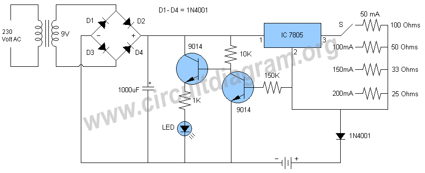
Schematic and description of a simple automatic NiMH battery charger circuit using IC 7805 with multiple selectable current options for charging. The described circuit is a straightforward automatic charger designed for Nickel-Metal Hydride (NiMH) batteries. It utilizes the IC 7805...

This circuit is designed to charge between one and twelve NiCd cells using a car battery. With switch S1 set to the normal position, it is capable of charging up to six cells. The circuit operates by utilizing a car...
This circuit is used to measure the voltage on a 12V (nominal) lead acid rechargeable battery system. It was specifically designed for use in solar powered systems, but is general enough that it can be used for automotive or...
A portable phone charger designed for a Siemens mobile phone has been updated to include a printed circuit board (PCB), a USB connector, and enhanced current capabilities. The new charger utilizes a step-up converter based on the TPS61032, which...
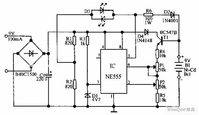
An automatic Ni-Cd battery charger circuit is depicted in the provided image. The internal comparator of the NE555 timer is configured to a reference voltage of 4.7V using a Zener diode. When the voltage at pin 6 exceeds this...
This project originated from the need for a Li-ion charging circuit that offers more flexibility than typical do-it-yourself circuits while being more affordable than programmable computerized chargers. The primary objective was to design, build, test, and share a charger...