
EMP Generator Schematic

The EMP generator design described involves utilizing the high-voltage flash circuits found in disposable cameras. These circuits are capable of generating a significant voltage, typically in the range of 300 to 400 volts, which is suitable for creating an electromagnetic pulse (EMP) effect. The basic components of the circuit include a capacitor, a transformer, and a discharge coil.
The disposable camera flash circuit operates by charging a capacitor through a low-voltage power supply, which is usually a small battery. Once the capacitor reaches its maximum charge, the circuit triggers the flash mechanism, discharging the stored energy through a transformer. This transformer steps up the voltage to a much higher level, which is then delivered to the discharge coil.
The discharge coil is a critical component of the EMP generator. It is designed to create a rapidly changing magnetic field when energized. The design of the coil, including the number of turns and the wire gauge, will significantly affect the efficiency and effectiveness of the EMP produced. A larger coil with more turns will typically generate a stronger magnetic field, leading to a more pronounced EMP effect.
Safety precautions are essential when working with high-voltage circuits, as the components can pose serious risks. Proper insulation, the use of protective gear, and adherence to safety guidelines are imperative when assembling and testing the EMP generator.
The instructable planned for this project will provide step-by-step guidance on the construction process, including a list of materials, circuit diagrams, and safety tips. This will enable individuals interested in replicating the design to do so while understanding the underlying principles and potential hazards associated with high-voltage electronics.These are my plans for an EMP Generator. It uses flash circuits from disposable cameras to power the coil. I plan to make an instructable of it soon.. 🔗 External reference
Related Circuits

The device utilizes the USB boot HID keyboard protocol. When connected, it can detect changes in the keyboard LED states (caps lock, num lock, scroll lock), which the firmware uses to initiate new password generation (indicated by four LED...
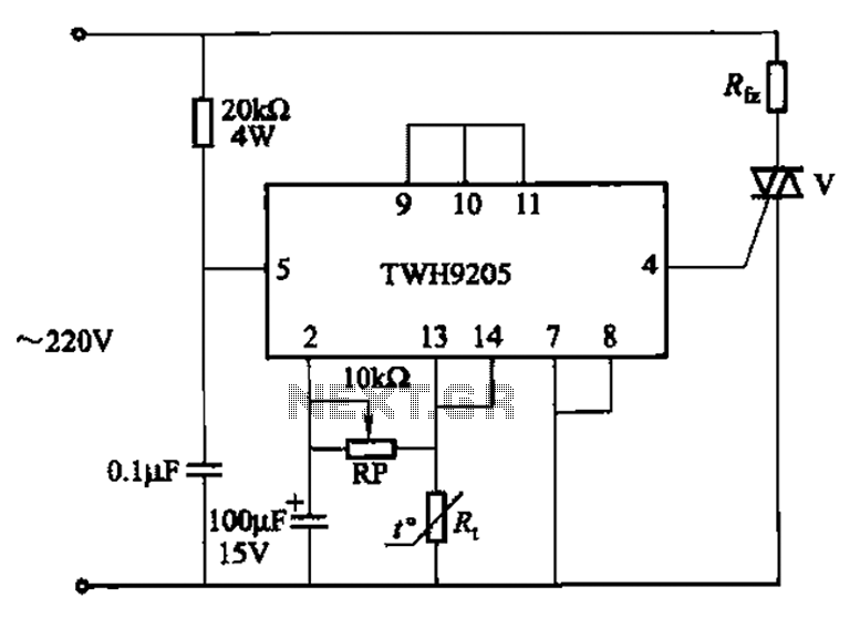
This circuit is used for temperature control in various heating equipment such as water heaters, microwave ovens, air conditioners, refrigerators, fans, and automatic fire extinguishing devices. It includes a negative temperature coefficient (NTC) thermistor as the temperature sensing element...
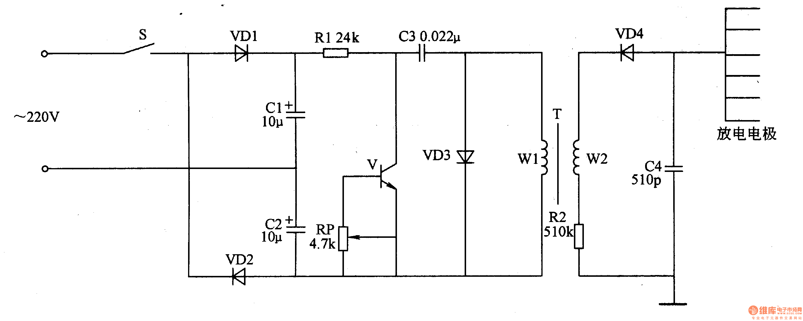
This negative oxygen ion generator circuit consists of a full-wave dual voltage rectifier circuit, a pulse oscillation circuit, and a negative high voltage generation circuit, as illustrated in figure 9-116. The dual voltage rectifier circuit is constructed using diodes...
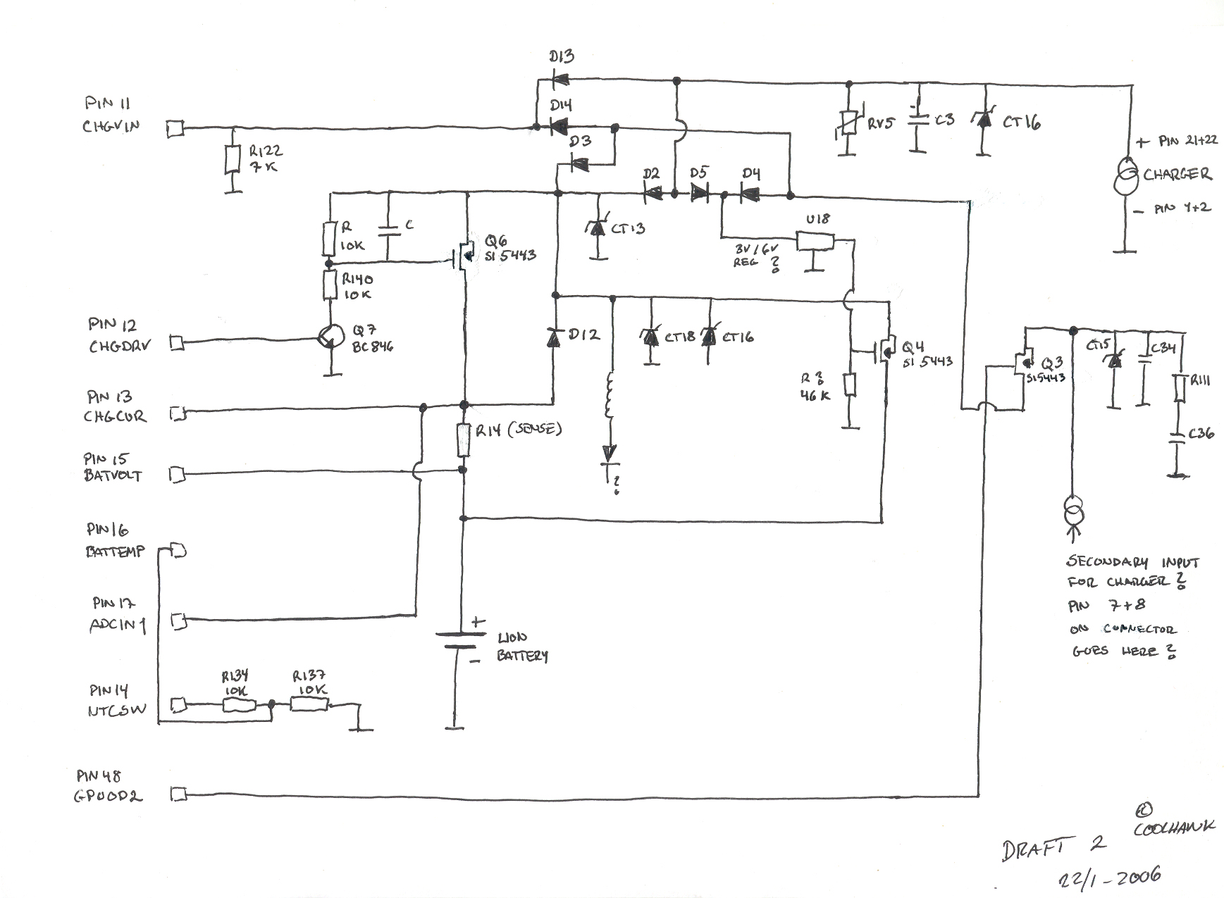
This is a basic hand-drawn schematic version 2. It will be transferred to Protel later when time permits. However, it provides a useful overview of the circuit, which can be charged from two different sources: USB or a standard...

Noise level measured into 75ohm 3.1kHz BW using Siemens D2006 level meter: -80dBU (77.5mV) from zero to 1MHz and drops 3dB on 17MHz. Decrease the first coupling capacitor (68nF) to 10nF to increase the lower limit to 50kHz. The...
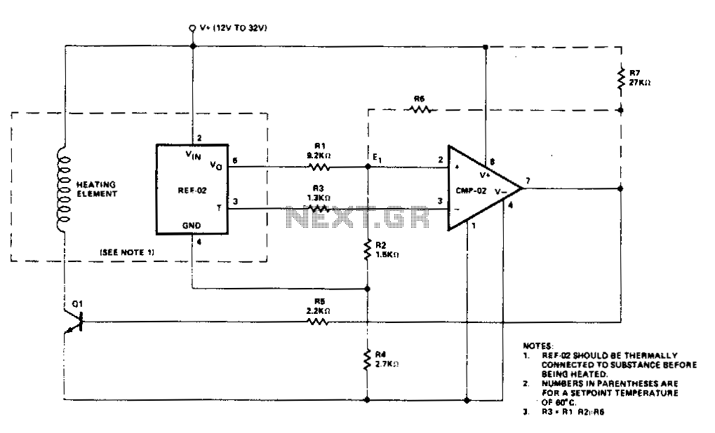
Temperature control is accomplished using the REF-02 +5 V Reference/Thermometer in conjunction with the CMP-02 Precision Low Input Current Comparator. The CMP-02 activates a heating element driver (Q1) whenever the current temperature falls below a predetermined setpoint, which is...