
Negative oxygen ion generator 4

The negative oxygen ion generator circuit is designed to produce a flow of negative oxygen ions, which can be beneficial for air purification and improving air quality. The full-wave dual voltage rectifier circuit converts the incoming AC voltage into a pulsating DC voltage, utilizing diodes VD1 and VD2 for rectification. Capacitors C1 and C2 serve to smooth the output voltage, ensuring a more stable DC supply for the subsequent stages of the circuit.
The pulse oscillation circuit is crucial for generating the necessary high-frequency oscillations that drive the negative ion generation process. Transistor V acts as a switch, controlled by the voltage across potentiometer RP, which allows for fine-tuning the oscillation frequency. Resistor R1 provides necessary biasing for the transistor, while capacitor C3 aids in determining the oscillation frequency along with the characteristics of diode VD3, which rectifies the oscillating signal to maintain the pulse shape required for the boost transformer.
The boost transformer (T) plays a vital role in stepping up the voltage to the high levels required for ion generation. The negative high voltage generation circuit utilizes two windings of the transformer to achieve the desired output voltage. The high voltage silicon rectifier stack (VD4) is employed to convert the high-frequency AC output from the transformer into a high DC voltage suitable for ion generation. Resistor R2 and capacitor C4 are included to filter and stabilize the high voltage output, ensuring that the circuit operates efficiently and reliably.
Overall, this circuit design integrates various components to effectively generate negative oxygen ions, contributing to applications in air purification and enhancing environmental conditions. The careful selection and arrangement of components are essential for optimizing performance and ensuring the longevity of the device.This negative oxygen ion generator circuit is composed of full wave dual voltage rectifier circuit, pulse oscillation circuit and negative high voltage generation circuit, it is shown in the figure 9-116. The dual voltage rectifier circuit is made of diodes VD1, VD2, and capacitors C1, C2. The pulse oscillation circuit consists of transistor V, re sistor R1, potentiometer RP, capacitor C3, diode VD3 and once winding of boost transformer T. The negative high voltage generation circuit is composed of twice winding of T, high voltage silicon rectifier stack VD4, resistor R2 and capacitor C4. 🔗 External reference
Related Circuits

Part of the challenge is that multiple capacitors and resistors are present in the RIAA circuit. This is derived from the Harman-Kardon schematic. The information for the Citation IV is not readily available, but it is simpler to replace...
There are two main types of oscillators: the most common is the Wein Bridge oscillator variety, which has low distortion but offers only sine wave output and can suffer from amplitude bounce as frequency changes. The second type, which...
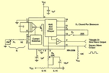
For measurement purposes in the electronics laboratory, signals of various frequencies and waveforms are frequently required. A standard function generator typically provides sine, triangular, and square wave outputs. The frequency must be adjustable and should encompass at least the...
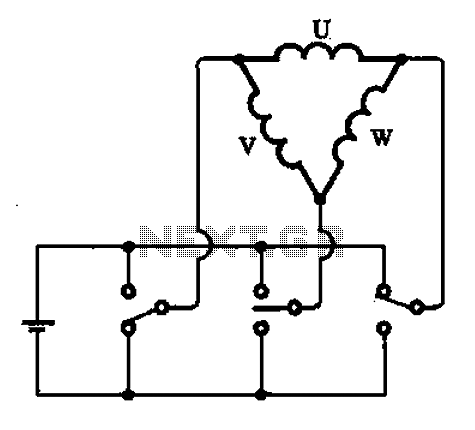
A stator coil connection illustrates the structure and connections of the stator coil. Figure (A) depicts a triangular connection, while Figure (B) illustrates a star connection, presented in two forms. The stator coil is a critical component in electric machines,...
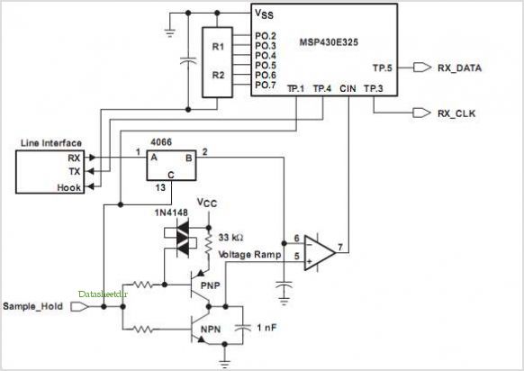
The FX919A is a CMOS integrated circuit that includes all necessary baseband signal processing and Medium Access Control (MAC) protocol functions for a high-performance 4-level Frequency Shift Keying (FSK) Wireless Packet Data Modem. It interfaces with the modem host...
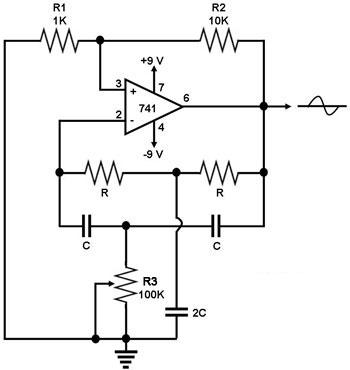
This circuit generates a sine wave using a single operational amplifier (741). The feedback loop of the op-amp includes a twin-T filter connected between its output and inverting input. Positive feedback for oscillation is provided by resistor R2. The...