
Enhanced AE1169 made lock circuit diagram

The AE1169 enhanced lock system circuit is designed to provide a robust security solution with advanced user interaction capabilities. The core of the design revolves around a microcontroller that interprets inputs from the 12-bit quasi-keyboard. The keyboard is structured to allow multiple configurations, enhancing flexibility in usage scenarios. The keys are categorized as functional keys, with specific roles assigned to each, such as the '*' key for confirmation and an additional key for error clearance.
Upon pressing the lock button, the system initiates a keyboard scan to detect which key has been pressed. The states of S1, S2, and S3 are critical as they determine the operational mode of the lock system. The internal logic circuitry interprets these states to execute the appropriate response, such as activating the alarm relay K1 or controlling relay K2, which may trigger an alarm or lock mechanism.
The design also incorporates a fail-safe mechanism. If a user inputs an incorrect password, the clear key can be utilized to reset the input without needing to confirm through the '*' key. This feature minimizes frustration for users and enhances the efficiency of the locking mechanism.
The switch configurations (S1, S2, S3) allow for easy toggling between different operational modes, enabling collective access for multiple users, as well as modes for single-user access. This flexibility is particularly beneficial in environments where access control needs to be managed dynamically.
In summary, the AE1169 enhanced lock system circuit offers a sophisticated approach to security, combining user-friendly input methods with reliable electronic control mechanisms, suitable for various applications requiring secure access management. As shown in Figure is a circuit diagram of an enhanced lock the AE1169. AE1168 enhanced when the lock button is pressed, AE1168 through the keyboard scan to determine the corre sponding button, and in accordance with S1, S2, S3 state, the internal logic analysis treated, and the alarm relay K1, * K2 corresponding relay control. Circuit 12-bit quasi-keyboard, which represents the * key to confirm; key is the clear key, if they enter the wrong password, as long as the failure to confirm the * key, you can press this key to clear the input error.
By switching S1, S2, S3 can easily achieve more than the collective *, multiplayer and single * alone * function.
Related Circuits
The motor control circuit depicted in the image utilizes the LM339 comparator among other components. When the input control signal is high (PWL), comparators A and A3 activate the power amplifier circuit, which consists of A4, VT5, and VT6,...
The wireless FM transmitter circuit described here includes an additional RF power amplifier stage following the oscillator stage, which increases the power output to 200-250 mW. The wireless FM transmitter circuit functions by modulating audio signals onto a radio frequency...
This PWM controller circuit is suitable for managing small motors with a maximum current consumption of 2A. For higher currents, additional cooling is required. The PWM (Pulse Width Modulation) controller circuit is designed to efficiently control the speed of small...
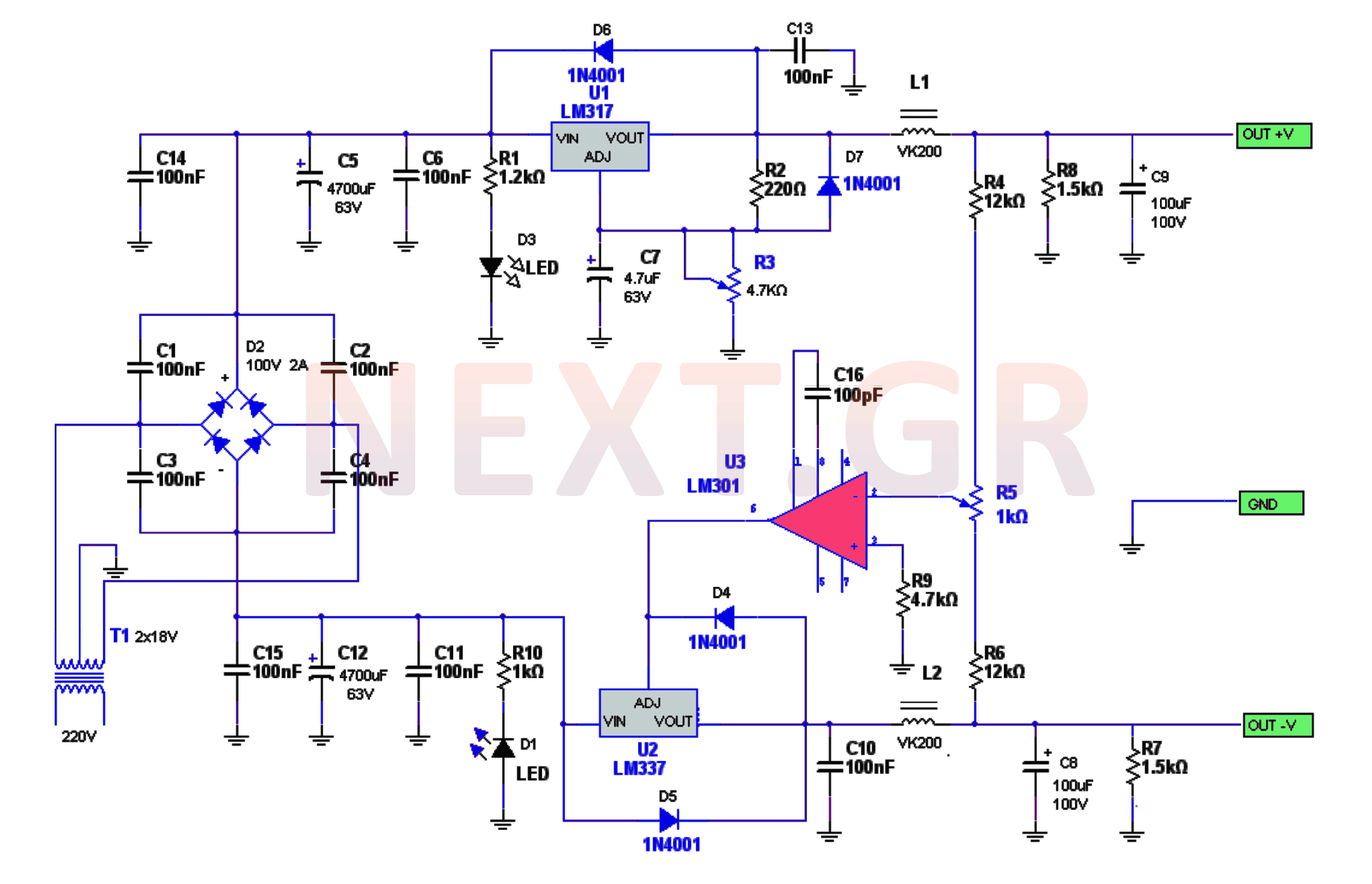
The power supply circuitry includes a 220/2 * 18V / 3.5A transformer, a rectifier, a smoothing filter, a power amplifier (LM301), and two regulators (LM317 and LM337). The voltage from the transformer is rectified by a bridge rectifier. Capacitors...
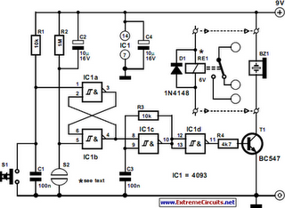
The following circuit illustrates a Simple Moisture Detector Circuit Diagram. This circuit is based on the 4093 IC. Features include the ability to detect a certain level of moisture. The Simple Moisture Detector Circuit utilizes the 4093 integrated circuit, which...
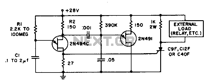
Time delays ranging from 0 milliseconds to over three minutes can be achieved with this circuit without the need for tantalum or electrolytic capacitors. The timing interval begins when power is applied to the circuit. At the conclusion of...