
Simple Moisture DetectorCircuit Based On The 4093 IC
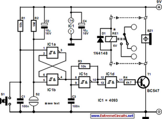
The Simple Moisture Detector Circuit utilizes the 4093 integrated circuit, which is a quad NAND gate with Schmitt trigger inputs. This component is chosen for its capability to provide stable switching characteristics, which are essential for moisture detection applications. The circuit typically consists of a few additional passive components, including resistors and capacitors, configured to establish the desired sensitivity and response time.
In operation, the moisture sensor typically consists of two conductive probes that are inserted into the soil or the medium being monitored. When moisture is present, it creates a conductive path between the probes, altering the voltage level at the input of the 4093 IC. The Schmitt trigger action ensures that the output switches cleanly and reliably between high and low states, depending on the moisture level detected.
The output from the 4093 can be connected to various devices, such as an LED indicator, which turns on when moisture is detected, or it can trigger a relay to activate a watering system. The circuit can be powered by a simple battery or an external power supply, making it versatile for different applications.
To enhance the circuit’s performance, additional components such as variable resistors can be included to adjust sensitivity, and capacitors can be added to filter noise and stabilize the circuit operation. Overall, this Simple Moisture Detector Circuit is a practical solution for monitoring moisture levels in agricultural and gardening applications, ensuring optimal conditions for plant growth.The following circuit shows about Simple Moisture Detector Circuit Diagram. This circuit based on the 4093 IC. Features: when a certain moisture .. 🔗 External reference
Related Circuits
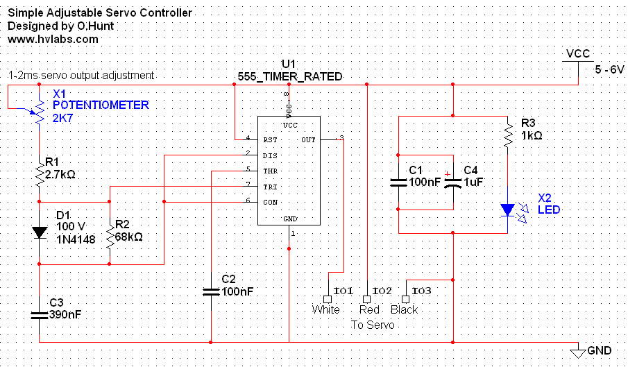
The circuit is straightforward. A 555 timer integrated circuit (IC) is utilized to generate a pulse every 20 milliseconds, with a duty cycle ranging from 5% to 10% (1-2 milliseconds). All components used are standard parts. This circuit can...
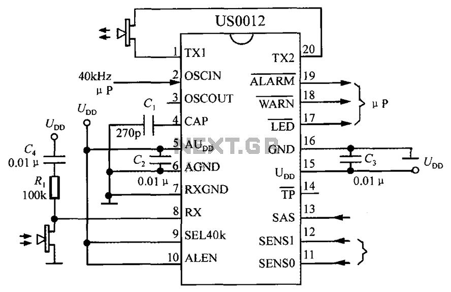
The circuit consists of the US0012 ultrasonic interference detection system, as illustrated in the accompanying figure. When the SEL40k termination is set to high, it selects a clock frequency of 40kHz. The US0012 module can perform several tasks: it...
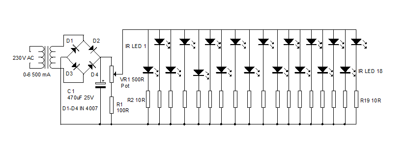
An infrared illuminator emits light in the infrared spectrum and is widely used in night vision cameras to capture images in the dark, particularly in applications such as CCTV cameras. Infrared illuminators are essential components in various surveillance and imaging...
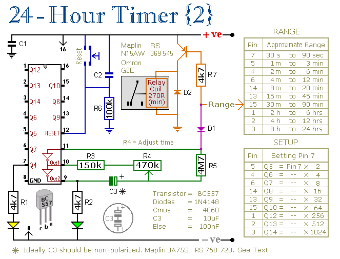
These two circuits are multi-range timers that offer periods of up to 24 hours and beyond. They can function as repeating timers or single-shot timers. Both circuits are fundamentally the same, with the primary distinction being their behavior in...
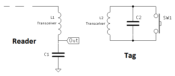
A coil of approximately 1 mH is utilized for both sides of the circuit. Given a chosen frequency of 125 kHz, the required capacitor value is calculated to be 1.62 nF, with a standard value of 1.5 nF selected....
The following circuit illustrates the sensor circuit diagram for automatic room lights. This circuit is based on the CD4017 integrated circuit (IC) and features the use of two light-dependent resistors (LDRs). The automatic room light circuit utilizes the CD4017 decade...