
ESR & Low Resistance Test Meter

The circuit for measuring the equivalent series resistance (ESR) of electrolytic capacitors is designed to operate efficiently at a frequency of 100 kHz. The oscillator circuit, using inverter IC1d, generates a stable square wave that is then processed by the J-K flip-flop (4027) which ensures a balanced duty cycle for the test signal. The alternating activation of the bilateral switches (4066) allows for the application of the test signal across the capacitor while maintaining a controlled environment to prevent damage from charged capacitors.
The series resistance included in the circuit is critical for limiting the current flowing into the capacitor under test, thereby protecting both the capacitor and the measuring components. The diodes (D1, D2, D3, and D4) play a protective role, ensuring that the signals do not exceed safe levels, which is particularly important when dealing with potentially charged capacitors.
The sample and hold mechanism utilizing the 1 µF capacitors is essential for capturing the average DC level that corresponds to the ESR of the capacitor being tested. This design choice simplifies the measurement process by filtering out AC components, allowing for a clear representation of the ESR on the digital multimeter.
Calibration of the circuit is methodical, requiring adjustments to various variable resistors (VR1, VR2, VR3, and VR4) to ensure accuracy in readings. The procedure includes setting the frequency, ensuring a zero voltage reference, and confirming current flow through the circuit. The final step of adjusting the meter to read the voltage across a known resistor ensures that the system is correctly calibrated for accurate ESR measurement. This comprehensive approach to design and calibration ensures that the circuit remains reliable and effective for testing electrolytic capacitors in various applications.As electrolytic capacitors age, their internal resistance, also known as "equivalent series resistance" (ESR), gradually increases. This can eventually lead to equipment failure. Using this design, you can measure the ESR of suspect capacitors as well as other small resistances. Basically, the circuit generates a low-voltage 100kHz test signal, wh ich is applied to the capacitor via a pair of probes. An op amp then amplifies the voltage dropped across the capacitor`s series resistance and this can be displayed on a standard multimeter. In more detail, inverter IC1d is configured as a 200kHz oscillator. Its output drives a 4027 J-K flipflop, which divides the oscillator signal in half to ensure an equal mark/space ratio.
Two elements of a 4066 quad bilateral switch (IC3c & IC3d) are alternately switched on by the complementary outputs of the J-K flipflop. One switch input (pin 11) is connected to +5V, whereas the other (pin 8) is connected to -5V. The outputs (pins 9 & 10) of these two switches are connected together, with the result being a ±5V 100kHz square wave.
Series resistance is included to current-limit the signal before it is applied to the capacitor under test via a pair of test probes. Diodes D1 and D2 limit the signal swing and protect the 4066 outputs in case the capacitor is charged.
A second pair of leads sense the signal developed across the probe tips. Once again, the signal is limited by diodes (D3 & D4) before begin applied to the remaining two inputs of the 4066 switch (pins 2 & 3 of IC3a & IC3b). These switches direct alternate half cycles to two 1 F capacitors, removing most of the AC component of the signal and providing a simple "sample and hold" mechanism.
The 1 F capacitors charge to a DC level that is proportional to the test capacitor`s ESR. This is differentially amplified by op amp IC4 so that it can be displayed on a digital multimeter 10 © will be represented by 100mV, 1 © by 10mV, etc. To calibrate the circuit, first adjust VR1 to obtain 100kHz at TP3. Next, momentarily short the test probes together and adjust VR4 for 0mV at pin 6 of IC4. That done, set your meter to read milliamps and connect it between TP4 and the negative (-) DMM output.
Apply -5V to TP2 and note the current flow, which should be around 2. 1mA. Transfer the -5V from TP2 to TP1 and adjust VR2 until the same current (ignore sign) is obtained. Remove the -5V from TP1. Again, set to your meter to read volts and connect it to the DMM outputs. Apply the probes to a 10W resistor and adjust VR3 for a reading of 100mV. Finally, ensure that all capacitors to be tested are always fully discharged before connecting the probes. 🔗 External reference
Related Circuits
The Model LM-13 Crystal Calibrated Frequency Indicating Equipment has been specifically designed to provide a simple, accurate, and reliable frequency indication for the crystal calibrated type, intended for use in the U.S. Naval radio service. It is adaptable for...
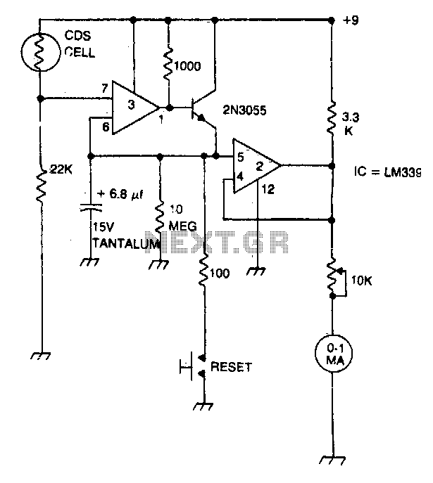
A strobe light meter captures the peak flash intensity and retains it long enough to provide a reading. The reset button must be pressed prior to each measurement. The strobe light meter operates by detecting the peak intensity of light...

This article is relevant only to readers whose bicycle lights are powered by a dynamo. The regulations regarding bicycle lights in the United Kingdom are more stringent. Dynamo-powered bicycle lights are an essential component for cyclists, providing illumination without the need...
This 4.5-digit digital voltmeter (DVM) circuit is designed around the Maxim ICL7129ACPL analog-to-digital converter (A/D converter) and an LCD driver. It utilizes an ICL8069 CCZR 1.2-V band-gap reference diode for voltage referencing. The switch S2a-b-c allows the selection of...

Pulse size and width are independent of pulse energy or other properties of the event. Geiger-Mueller tubes have reduced sensitivity to non-gamma-ray radiation and exhibit poor dose-rate calibration accuracy. They are commonly used due to their favorable balance of...
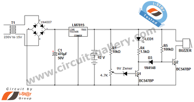
This is a straightforward 12V rechargeable smart battery charger circuit. It can be utilized as a charger for car batteries, inverter batteries, emergency light batteries, and more. An automatic indicator alarm circuit accompanies this battery charger schematic. The primary...