
Simple battery charger circuit and battery level indicator with low battery recharge alarm

The 12V rechargeable smart battery charger circuit is designed to efficiently charge various types of batteries, making it versatile for multiple applications. The circuit typically comprises several key components: a transformer, rectifier, voltage regulator, and various indicator elements.
The transformer steps down the AC voltage from the mains to a suitable level for charging the battery. Following this, the rectifier converts the AC voltage into DC voltage, which is essential for battery charging. A smoothing capacitor is often included to reduce voltage ripple, ensuring that the battery receives a steady charging current.
The voltage regulator maintains a consistent output voltage, which is crucial for preventing overcharging and prolonging battery life. This component ensures that the voltage remains within safe limits as the battery charges.
The automatic indicator alarm circuit is an important feature of this charger. It includes a buzzer and an LED indicator. The buzzer is activated when the battery voltage falls below a certain threshold, alerting the user that the battery is discharged and requires recharging. Simultaneously, LED1 provides a visual indication of the battery's status; when the battery is charged, LED1 lights up, and it turns off when the battery voltage drops below the critical level.
In summary, this smart battery charger circuit not only facilitates efficient battery charging but also includes safety features that enhance user convenience and battery longevity. Its design caters to a variety of battery types and applications, making it an essential tool for maintaining battery health in everyday use.This is a simple 12V rechargeable smart battery charger circuit. You can use this best battery charger circuit as car battery chargers, Inverter battery charger, Emergency light battery charger etc. An automatic indicator alarm circuit also comes along with this battery charger schematic. The main advantage of this indicator is that a buzzer infor ms us when the battery needs recharge. This circuit schematic definitely helps for your daily life battery charging applications. Also Read: When battery voltage goes below a particular value, LED1 stops glowing and the buzzer produces sound indicating that the battery has been discharged and it needs recharge. 🔗 External reference
Related Circuits
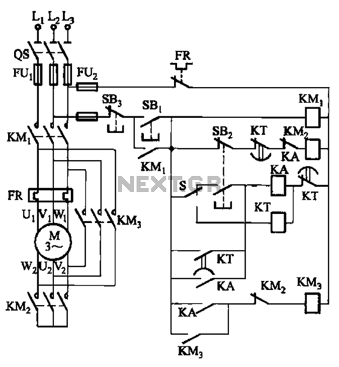
The circuit is depicted. It is capable of both manual and automatic control. The circuit in question is designed to facilitate dual modes of operation: manual and automatic control. This versatility allows users to engage with the system according to...
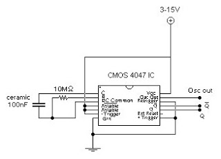
This circuit generates a digital square wave that can be displayed directly or utilized to drive additional circuits. It employs the CMOS 4047 Low-Power Monostable/Astable Multivibrator, as referenced in Tom Duncan's "Adventures with Digital Electronics" book, to control a...
There is no substitute for sheer power—low-efficiency speakers, outdoor sound systems, or perhaps the full dynamic range of a high-power amplifier. Whatever the requirement, this super power module should meet the needs. The amplifier can be divided into three...
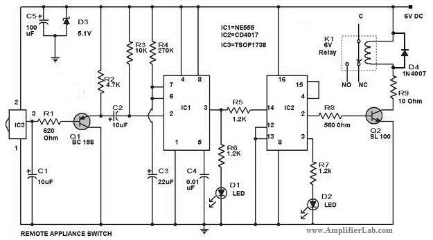
The circuit diagram of a remote-controlled appliance switch circuit includes two main components: IC1 (NE 555) and IC2 (CD 4017). The remote-controlled appliance switch circuit is designed to allow users to control electrical appliances wirelessly. The heart of this circuit...
A purchase was made of the EDE702 along with an LED-backlit LCD character display. After acquiring the EDE702, it was determined that it lacked sufficient integration with HD44780-compatible displays to justify its cost. However, utilizing it was preferable to...
GND and VCC are positioned perpendicularly to the other pins in the circuit diagrams, while the actual Z80 is a DIP with no pins in these locations. This arrangement complicates the readability of the circuit diagram, necessitating a mapping...