
Experimental Pendulum Clock
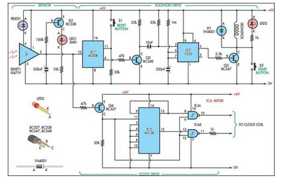
The rod extends some 15 cm below the bob and is fitted with large washes at the lower end. Note that for a pendulum to beat in seconds, there must be 99. 4cm distance between the support and the centre of mass of the pendulum. Between the bob and the lower end is a 5mm wide white reflector facing back. Below the rod and 15mm to the left is the impulse solenoid, with a core but no actuator attached. The circuit comprises of four parts: (1) the sensor; (2) the counter and solenoid driver; (3) the clock driver; and (4) the clock. The sensor is built on its own small piece of strip board and is located on the centre line of the backboard behind the reflector.
It utilises a Sharp IS471F infrared modulated detector (Farnell cat. 414-2860) to eliminate interference from external light sources. The infrared emitter (IRLED1) must be mounted near to the detector (IRDET1) but be masked from it. The emitter radiates a coded signal toward the reflector. As the pendulum passes the centre line it reflects the signal back to the detector, which then gives a negative-going output pulse on pin 2. This makes the surface-mount LED (LED1) flash once. It also sends a signal to the counter and clock driver circuits on the main circuit board. Pulses from the sensor are fed into IC1, a 4020 14-stage ripple counter. The counter`s output (pin 6) goes high every 128 counts (seconds). These long duration pulses are inverted by transistor Q1 and differentiated by the 10nF capacitor and 22kO resistor, providing a narrow trigger pulse for a 7555 CMOS timer (IC2).
The 7555 is wired as a monostable, driving the base of transistor Q3 with a relatively short pulse width suitable for energising the impulse solenoid. LED2 flashes in unison with solenoid pulses, and can be mounted right on the solenoid as a visual aid.
Pushbutton switch S2 is used to provide gentle starting pulses to get the pendulum swinging smoothly at the outset. Switch S1 resets the counter to zero. With this arrangement, the pendulum is set swinging and when it is to the left of centre, S1is pushed.
Thus, the pendulum moves right to left on even numbered counts. At the 128th count, the solenoid gives a shot pull to the left just as the pendulum is passing through the centre line and moving right to left. The distance of the solenoid below the pendulum is adjusted so that it does not jerk the pendulum but adds a gentle nudge.
The clock driver circuit also derives its timing from the output of the sensor. Negative-going pulses from the sensor are inverted by Q4 before being fed into a 4013 flipflop. On the output side, pins 12 & 13 go high in turn for one second. These pulses are too long to directly drive the clock coil, so they`re logically anded with the short pulses from the sensor using two gates of a 4093 NAND Schmitt trigger (IC4). The outputs from these gates then drive an adapted quartz clock movement. A suitable clock can be made from a standard quartz movement by isolating the coil and removing the battery.
See SILICON CHIP, Dec. 1996, page 38 for full instructions or October 2001 page 37 for brief notes. This is an experimental clock so you may have to try various solenoids to find one that works for you. If necessary, the solenoid pulse duration can be changed by varying IC2`s timing components. If the suspension is too stiff, try impulsing at 64 beats from pin 4 of IC1, but note that the aim is to get the freest pendulum movement possible.
The Synchronome and Hipp clocks were impulsed at 30-second intervals, so your clock could be even better. In the prototype, the reflector was made from the back 🔗 External reference
Related Circuits
A NIXIE tube was mounted on a wooden cigar box, with the anode connected through a large series resistor to the live wire of a 220V mains supply. Touching one of the cathodes caused the numbers to glow, sparking...
28 LED Clock Timer Circuit. This is a programmable clock timer circuit that uses individual LEDs to indicate hours and minutes. Twelve LEDs can be arranged in a circle to represent the 12 hours of a clock face, along with...
U1 is a 3817 integrated circuit produced by Fairchild Corporation. It is capable of directly driving a display and can operate in both 12-hour and 24-hour formats. Additionally, it can generate a clock sound and activate radios at scheduled...
As a followup to my VCR Pong project, here is a gadget that is actually useful in the Real World! It superimposes the time of day, in "HH MM SS" format, in the bottom right-hand corner of an existing...
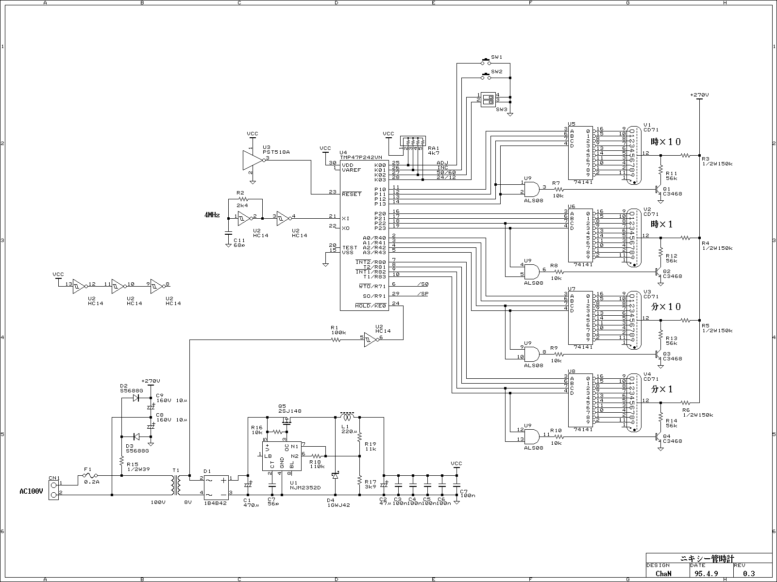
Because of the nixie-tube is a gas tube, it requires relatively high-voltage supply. Judging from archives, from 180 to 300 volts are used for supply voltage. In this project, 270 volts from rectified 100V line voltage directly is used....

The Pyro Propeller Clock POV schematic is relatively straightforward. It consists of three primary components: the power supply utilizing a 7805 voltage regulator, the LED output control managed by a PIC18F252 microcontroller and a 74LS373 latch, and the 'home'...