
Nixie-Tube Clock

The nixie tube is a type of gas discharge tube that operates by ionizing a low-pressure gas, typically neon, to produce visible light. This requires a high-voltage power supply, typically in the range of 180 to 300 volts, to energize the tube and allow it to display numerical digits. In this specific application, a supply voltage of 270 volts is derived from a rectified 100V AC line voltage.
The circuit design must ensure that the high-voltage components are properly isolated to prevent any accidental contact, as the entire circuit is not insulated from the power line. The use of appropriate insulation materials and safety precautions is critical when handling such high voltages.
The power supply section of the circuit typically includes a transformer to step up the voltage, followed by a rectifier to convert the AC voltage to DC. A filter capacitor is usually employed to smooth the rectified output, providing a stable high voltage for the nixie tube operation.
The nixie tube itself is connected to a high-voltage driver circuit, which may consist of transistors or high-voltage integrated circuits capable of switching the high voltage on and off to control the display.
It is essential to include proper fusing and circuit protection to safeguard against overcurrent conditions, which could lead to circuit failure or pose a safety hazard. Furthermore, all components must be rated for high voltage operation to ensure reliability and safety during operation.
In summary, while the circuit is straightforward in design, significant care must be taken to ensure safety and reliability when working with high-voltage nixie tube applications.Because of the nixie-tube is a gas tube, it requires relatively high-voltage supply. Judging from archives, from 180 to 300 volts are used for supply voltage. In this project, 270 volts from rectified 100V line voltage directly is used. It is very simple but whole of the circuit is not insurated from the power line, never touch any part of the circuit. 🔗 External reference
Related Circuits
The Clock Controller was designed as an exemplary application of the C programming language to manage timer0 interrupts, control a 7-segment LED display, and perform keypad scanning. It offers a 1-bit sink current output suitable for driving devices such...
The basic clock circuit is similar to the binary clock and uses 7 ICs to produce the 20 digital bits for 12 hour time, plus AM and PM. A standard watch crystal oscillator (32,768) is used as the time...

The concept involved removing the center page from a magazine and cutting it into four pieces to create a card suitable for a filing system. The front side of each card provided connections to the integrated circuit (IC), while...
The crystal-controlled SoftRock receivers developed by Tony Parks (KB9YIG) have played a significant role in introducing many individuals to Software Defined Radio (SDR). For those who prefer not to be limited to a single frequency, the SoftRock Ensemble receivers...
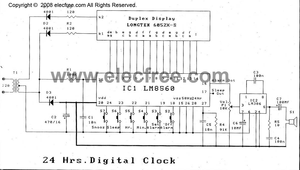
The digital time clock circuit is of great interest to electronic amateurs. The most popular clock ICs include the LM8361 and MM5387. Unfortunately, these ICs... The digital time clock circuit serves as an essential component for various electronic applications, providing...
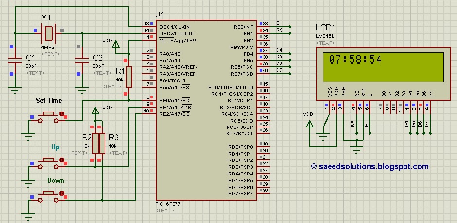
This tutorial on the PIC16F877 microcontroller addresses the question, "How to implement a controllable digital clock using the PIC16F877?" It utilizes the PIC16 simulator for demonstration purposes. The implementation of a controllable digital clock using the PIC16F877 microcontroller involves several...