
Experiments with coupled circuits

The described circuit operates by maintaining a stable frequency that alternates between two specific values. This frequency modulation allows for the analysis of the response characteristics of two distinct circuits when visualized on an oscilloscope. The oscilloscope serves as a crucial tool in this setup, providing a visual representation of the frequency spectrum, which includes the amplitude and phase response of the circuits under test.
The receiver circuit is designed to accept a low input voltage of 0.1 Volt peak-to-peak. This low-level signal is processed and amplified by the subsequent stages of the circuit. The detector circuit, which follows the receiver, is responsible for further processing the signal. It successfully amplifies the input voltage to approximately 5 Volts peak-to-peak. This amplification results in a voltage gain of 50 times, which is significant for applications requiring enhanced signal strength for further analysis or transmission.
The design of the circuit may involve various electronic components, such as operational amplifiers for amplification, resistors for setting gain levels, and capacitors for filtering out unwanted frequencies. Proper selection of these components is essential to ensure that the circuit operates efficiently within the desired frequency range while minimizing distortion and noise.
In practical applications, this type of circuit could be utilized in communication systems, signal processing, or instrumentation, where accurate frequency response measurements are critical. The ability to visualize the response curves on an oscilloscope allows engineers to assess the performance of the circuits and make necessary adjustments to optimize their functionality.The frequency is constant varying between two set values, on the oscilloscope screen you get a frequency spectrum with the response curve of the two circuits. The input voltage of the receiver is 0. 1 Volt peak-peak, the voltage across the detector circuit is about 5 Volt peak-peak, so we have a voltage gain of 50 times.
🔗 External reference
Related Circuits
The transformer OCL and capacitor C1 create a tank circuit, which is coupled with sufficient turns to drive the grid in the lower left-hand winding. The output circuit is connected through a separate winding. For optimal waveform characteristics in...
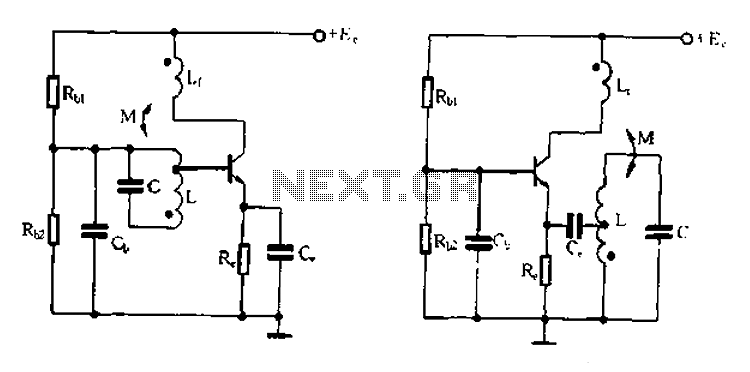
Base frequency selection, frequency-selective emitter type transformer coupled oscillator circuit The described circuit is a transformer-coupled oscillator that utilizes an emitter type configuration to achieve frequency selection. This type of oscillator is designed to generate signals at specific base frequencies,...
National Instruments Multisim now features microcontroller unit co-simulation capabilities, enabling the inclusion of a microcontroller, programmed in assembly or C code, within SPICE-modeled circuits. The MCU functionality in Multisim allows students, educators, and professional users to program MCUs in...
Here is the schematic diagram for a 20 Watt driver. I developed this circuit in 1985, and used it to build a lamp that found much use both as camping light and as emergency light during the then-frequent power...
A 6V to 12V DC converter circuit is designed to convert a lower voltage of approximately 6 volts to a higher voltage of 12 volts, albeit with a reduced current rating. This inverter circuit can deliver up to 800mA...
An integrated circuit is precisely that: an integrated circuit. These small packages combine numerous individual components to perform a specific function. They vary in shape and size depending on their complexity. They are categorized into functions such as audio,...