
Electronic Transformer Coupled Oscillators

The described circuit utilizes a transformer OCL (Output Capacitive Load) along with a capacitor C1 to create a resonant tank circuit. This tank circuit is essential for generating oscillations at a desired frequency, and its effectiveness is influenced by the coupling of the transformer windings. The coupling is designed to ensure that the grid of the triode is adequately driven to facilitate oscillation. The choice of triodes and Class B operation is vital, as these components contribute to maintaining a desirable waveform, specifically a sinusoidal output, which is critical for many applications.
The design considerations include the turns ratio between the anode and grid circuits, which is crucial for achieving the required voltage levels necessary for Class B operation. This ratio must be carefully calculated to ensure proper function when the circuit is driven by an amplifier stage. The use of single tubes is advantageous as it simplifies the design while the tank circuit's characteristics help sustain a sinusoidal waveform, even when the tube is inactive.
Grid biasing is handled through an RC circuit, which helps stabilize the grid voltage and ensures that the tube operates within its optimal parameters. The overall load on the tube is a combination of transformer losses, grid load, and the output, which must be accounted for in the design to prevent inefficiencies.
Transformer losses play a significant role in the overall performance, particularly in smaller oscillators where these losses can be substantial. The losses are categorized into core losses, gap losses, and copper losses. Copper losses are particularly noteworthy due to the high currents flowing through the tank circuit, necessitating larger wire sizes to handle the increased thermal and resistive effects. The design must also consider the inductance value, which is constrained by the tank circuit's Q factor and the desired harmonic content of the output.
For applications requiring low harmonic distortion, Class C oscillators may not be suitable due to their inherent design challenges. However, in scenarios where higher harmonic content is permissible, the transformer can be engineered for lower Q values, albeit at the cost of introducing non-sinusoidal waveforms.
The transformer design must take into account the significant turns required for the grid circuit, which are comparable to those of the plate circuit. This design choice is crucial as it influences the grid voltage swing, which can be limited by grid current during operation. The waveform characteristics during operation and non-operation phases are critical, as they impact the overall efficiency and stability of the oscillator.
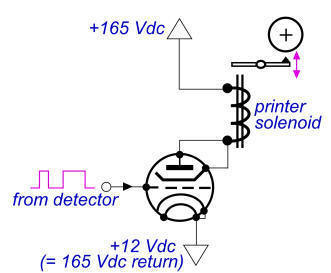
Lastly, predicting core losses in this type of design is complex due to the atypical waveforms produced. As a result, many designs will rely on empirical testing and iterative adjustments to achieve the desired performance specifications. The oscillation frequency's dependence on load variations necessitates careful consideration of Q factors, particularly in applications where frequency stability is paramount.Transformer OCL and capacitor C1 form a tank circuit, to which are coupled sufficient turns to drive the grid in the lower left-hand winding. The output circuit is coupled by a separate winding. For good wave shape in such an oscillator, triodes and class B operation are preferable. The ratio of turns between anode and grid circuits is determined by the voltage required for class B operation of the tube as if it were driven by a separate amplifier stage. Single tubes may be used, because the tank circuit maintains sinusoidal wave shape over the half-cycle during which the tube is not operating.
Grid bias is obtained from the RC2 circuit connected to the grid. In such an oscillator, tube load equals transformer loss plus grid load plus output. In small oscillators, transformer loss may be an appreciable part of the total output. This loss consists of core, gap, and copper loss. copper loss is large because of the relatively large tank current, and the wire size in the anode winding is larger than would be normally used for an ordinary amplifier. The gap is necessary to keep the inductance down to a value determined by the tank circuit Q or volt-amperes.
This in turn is dictated by the required harmonic content. The use and selection of core materials are approximately the same as those indicated in Filter Inductor Design and Powdered iron Cores. Class C oscillators are less desirable for very low harmonic requirements, because of the difficulty of designing tank circuits with sufficiently high Q.
Where large harmonic values can be tolerated, the transformer can be designed for low Q, but the wave form becomes non-sinusoidal. Transformer grid circuit turns are large, approximately the same as plate turns, and the grid voltage would be high if grid current did not limit the positive voltage swing.
During the half-cycle when the tube is operating, the voltage wave has a roughly rectangular shape, and during the rest of the cycle it peaks sharply to a high amplitude in the opposite direction. Core losses are difficult to predict because loss data are not normally available for such wave forms.
Consequently, designs of this type are usually cut-and-try. The frequency of oscillation varies with changes in load; hence low Q class C oscillators are to be avoided if good frequency stability is required. 🔗 External reference
Related Circuits
The 900 Hz tone is generated using an LC oscillator. The inductive component, "L," is provided by the inductance of the oscillator's output coupling transformer T1. This configuration is a variation of one of the two standard Hartley oscillator...

The thermostat electric circuit operates as depicted in the figure. It has three settings: off, low power (Lo), and high power (Peru HL). When the DIP switch SA is set to the Lo position, 220V AC is directed through...
Although it does not have the same charm as real mercury barometers with long glass tubes on pieces of carved and polished wood, the Torricelli barometer. The Torricelli barometer, named after the Italian scientist Evangelista Torricelli, is an instrument used...
This circuit will supply up to about 20mA at 12 volts. It uses capacitive reactance instead of resistance; and it doesn't generate very much heat. The circuit draws about 30mA AC. Always use a fuse and/or a fusible resistor...
A small (2 to 3 meters) neon electronic transformer circuit diagram is provided below. The described circuit diagram is intended for use with neon lighting systems, specifically those requiring a transformer to operate efficiently within a range of 2 to...
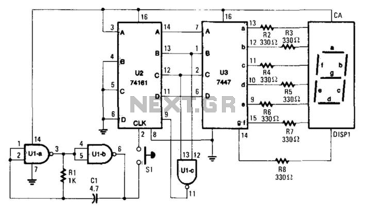
When the switch SI is activated, the counter U2 is controlled by the oscillator U1A/U1B, and the count ranging from 0 to 6 is displayed on DISP1. The resistor R1 and capacitor C1 determine the count rate, which must...