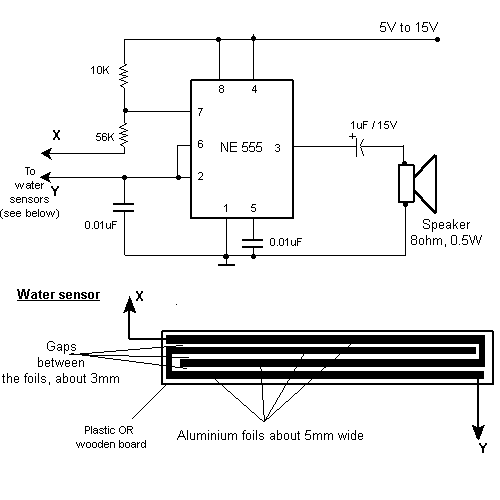
Siren Alarm Circuit

The ramp voltage from the low-frequency oscillator IC1 modulates IC2, thereby producing a rising and falling tone similar to the wail of police cars.
The described circuit utilizes a low-frequency oscillator (IC1) to generate a ramp voltage. This ramp voltage serves as the modulation signal for a second integrated circuit (IC2). The modulation of IC2 by the ramp voltage results in the generation of an audio signal that varies in frequency, creating a tone that rises and falls. This effect mimics the characteristic sound of police sirens, which typically feature a distinctive wailing pattern.
In this configuration, IC1 is designed to produce a linear ramp voltage over a defined period. The frequency of this ramp can be adjusted to control the pitch and rate of the tone produced. The output of IC1 is fed into the modulation input of IC2, which is configured as a sound generator or oscillator capable of producing audio frequencies.
IC2 interprets the ramp voltage from IC1 and adjusts its output frequency accordingly. As the ramp voltage increases, the output frequency of IC2 rises, producing a higher pitch tone. Conversely, as the ramp voltage decreases, the output frequency drops, resulting in a lower pitch tone. This continuous modulation creates the desired siren-like effect.
To enhance the performance of this circuit, additional components such as resistors, capacitors, and possibly a speaker or audio output stage may be included. These components can help filter the output signal, adjust the amplitude, and ensure that the sound is suitable for auditory applications. Proper tuning of the circuit elements will yield a clear and effective simulation of a police siren, making it useful for various applications in alarms, toys, or sound effects in multimedia projects. The ramp voltage from the low frequency oscillator 1C1 modulates IC2 thereby producing a rising and falling tone like the siren wail of police cars. 🔗 External reference
Warning: include(partials/cookie-banner.php): Failed to open stream: Permission denied in /var/www/html/nextgr/view-circuit.php on line 713
Warning: include(): Failed opening 'partials/cookie-banner.php' for inclusion (include_path='.:/usr/share/php') in /var/www/html/nextgr/view-circuit.php on line 713


