
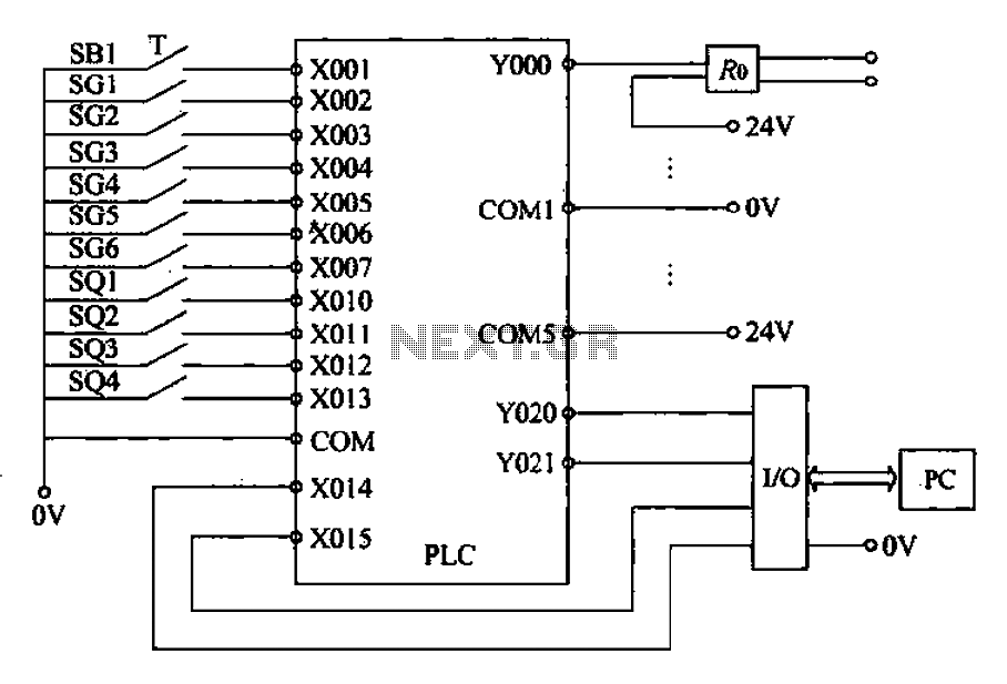
External wiring diagram of PLC
The described PLC system is designed to manage a complex automation task involving multiple input and output signals. The input signal path is structured to allow for seamless operation of the motor starter button and photoelectric switches, which are critical for detecting the presence of objects or the completion of tasks at various stations. The normally open contacts of the photoelectric switches ensure that the system remains inactive until triggered by an object, enhancing safety and efficiency.
The 18 output channels of the PLC facilitate control over various components, including motors and solenoids. The use of solid-state relays for driving AC contactors and inductive loads is a significant design choice, as it mitigates the risk of voltage spikes that could otherwise disrupt the PLC's operation. This isolation is crucial for maintaining the integrity of the control system and ensuring that the PLC can operate reliably in an industrial environment.
The Mitsubishi FX2N-48MR-O01 PLC is well-suited for this application, offering ample I/O capabilities and robust performance. The external wiring configuration, which includes specific designations for each control point, is essential for troubleshooting and maintenance. Each component, from the motor start button to the limit switches, is strategically placed to optimize the workflow of the robotic glazing process.
In summary, this PLC-based control system integrates various sensors and actuators to automate the glazing process efficiently. The careful consideration of input and output management, along with the use of solid-state relays for isolation, highlights the system's reliability and effectiveness in an industrial setting.1/0 defined PLC Table. Its input signal path 13, including: 1 motor starter button. 2, 3, 5, 7, 8, 9 station photoelectric switch normally open contact, move the CD machine 37 and 7 of the cylinder upper and lower limit switch, and spraying is completed and the response signal SF greenware position signal ARP. Output PLC has 18 road, including: 1 ~ 9 9 station motor control signal, transfer machine 37 and 7 CD rise and fall Yan electromagnetic control signal, transfer machine 37 and 7 CD motor control signal, the clamp solenoid control signal, and greenware position signal RI, and answering spraying Ends completion signal ASF.
Output control signals YO-Y17 is no direct drive AC contactor or solenoid valve, but is driven by solid state relays, so it will be PLC output interface circuit AC contactor or inductive loads such as solenoid valves to isolate, avoid the coil off current moment generated on PLC affected. The robot glazing peripheral device control system input and output points require control requirements, the system used Mitsubishi FX2N- 48MR-O01 type PLC.
Its external wiring circle tSB1 1 motor start button, SG1-SG6 were 2, 3, 5, 7, 8, 9 stations on the motor trip switch. soi and SQ2 for the transfer machine 37 cylinder upper and lower limit switch, SQ3 and SQ4 to transfer machine 7, cylinder soil bit and lower limit switch.
Related Circuits
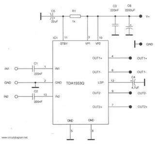
This is a 22-watt car stereo audio amplifier. The circuit is based on a single IC TDA1553 with a few peripheral components. This IC is designed for car audio applications. The TDA1553CQ integrates two 22-watt amplifiers with differential input...
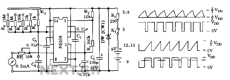
The tester comprises a dual time base circuit using a 556 timer and various RC components. The right side of the circuit features the 556 timer (556 1/2) along with resistors R2, R3, capacitors C2, C3, and additional components...
Chevy S-10 Blazer Ignition Control (IC) Circuit Wiring Diagram. The Chevy S-10 Blazer ignition control circuit is a critical component in the vehicle's ignition system, responsible for managing the timing and operation of the engine's spark plugs. The circuit typically...
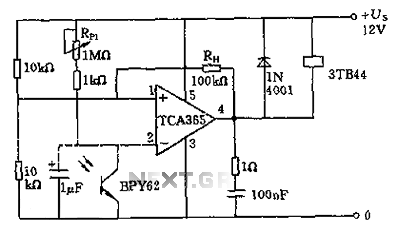
A bridge input circuit utilizing a phototransistor BPY62 and a power operational amplifier is capable of controlling power loads up to 8.5 kW. It features a voltage divider composed of two 10 kΩ resistors, creating a midpoint connection. The...
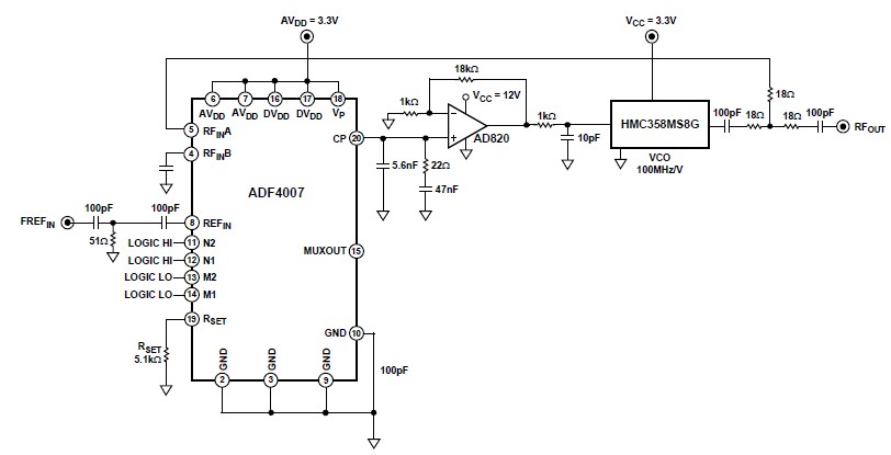
The ADF4007 high-frequency divider Phase-Locked Loop (PLL) synthesizer can be utilized in a variety of communication applications. It operates up to 7.5 GHz on the RF side and 120 MHz at the Phase Frequency Detector (PFD). The device includes...
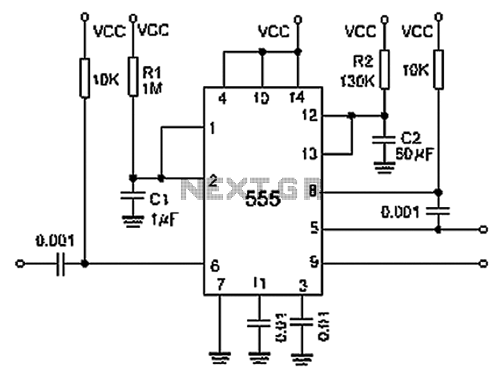
A 0.001 F coupling capacitor connects the output of the first half of a 556 timer to the input of the second half, providing an individual delay that equals the total delay. The 6-foot ground can immediately activate the...