
555 capacitance tester circuit diagram

The described tester circuit utilizes the 556 timer, which contains two independent timing circuits that can be configured in various ways. The astable multivibrator configuration on the right side of the circuit generates a continuous square wave signal. The frequency of oscillation is determined by the resistors and capacitors connected to it, allowing for precise timing control. The use of R2 and R3 in the formula for frequency highlights the relationship between resistance and capacitance in determining the oscillation rate, which is critical for accurate capacitance measurement.
On the left side, the one-shot circuit is essential for generating a pulse in response to the square wave output. The duration of this pulse is governed by the selected range resistors R4 to R8 and the capacitance Cx being measured, providing flexibility in measurement capabilities. The inclusion of a potentiometer (RP1) for calibration ensures that the measurements can be fine-tuned against known capacitance standards, enhancing the accuracy of the tester.
The circuit is capable of measuring a wide range of capacitance values, which is particularly useful in electronics for testing capacitors in various applications. The clear division of measurement ranges enables users to select the appropriate setting for the capacitance being tested, ensuring that the circuit operates within optimal parameters. The output current range from 100µA to 0.5mA indicates the circuit's ability to handle different capacitance levels, making it a versatile tool for engineers and technicians working with electronic components.The tester consists of an dual time base circuit 556 and a number of RC components and other components. Illustrated by the right half of the circuit 556 (556 1/2) and R2, R3, C2, C3 and other components astable multivibrator, the oscillation frequency f = 1.44 / (R2 + 2R3) C2. Parameters correspond icon the frequency of about 60Hz or so. The left half of 556 (556 1/2) and C4, range resistors R4 ~ R8 and measured capacitance Cx constitute one-shot trigger circuit, 5 feet at the low level period of the square wave output of the right half, monostable flip, one-shot pulse width depends on the range resistors R4 ~ R8 and Cx, ie, t = 1.1 (R4 ~ R8) Cx.
According to the measured capacitance Cx select a different size range. Cx different capacities, the 556 9-pin output level correspondingly different, after potentiometer RP1 connected mA current file table or multimeter. RP1 potentiometer for the correction, for full-scale calibration with standard capacitance. 556 feet of each waveform diagram shown in Fig. B. This circuit can be measured capacitance of 10pF ~ 1uF within range. Range divided 10p ~ 100p ~ 1000p ~ 0.01u ~ 0.1u ~ 1u, corresponding to the current range of 100uA ~ 0.5mA.
Related Circuits
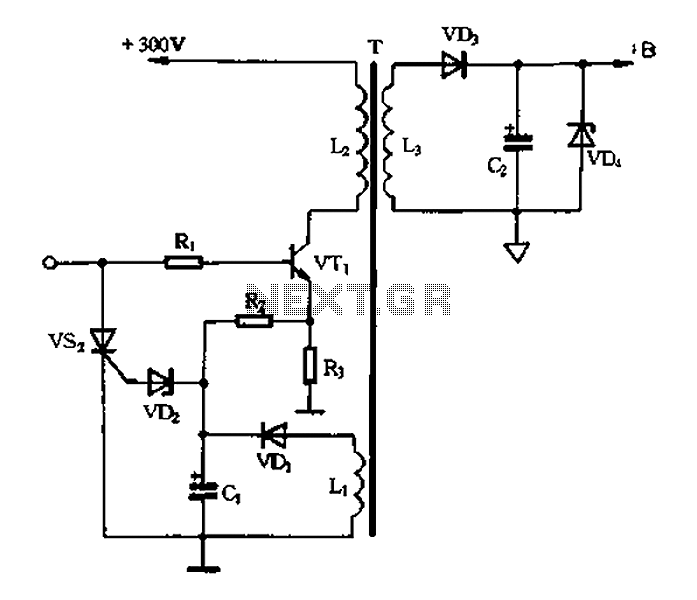
Color TV main power protection circuit The color TV main power protection circuit is designed to safeguard the television's power supply from various electrical anomalies, such as overvoltage, undervoltage, and short circuits. This circuit typically employs several components, including fuses,...
The DTMF codec stands for dual-tone multi-frequency codec. The multiple-channel infrared remote control switch circuit that incorporates the DTMF is depicted in the figure. It consists of an infrared remote control signal emitter, an infrared receiving signal amplifier, a...
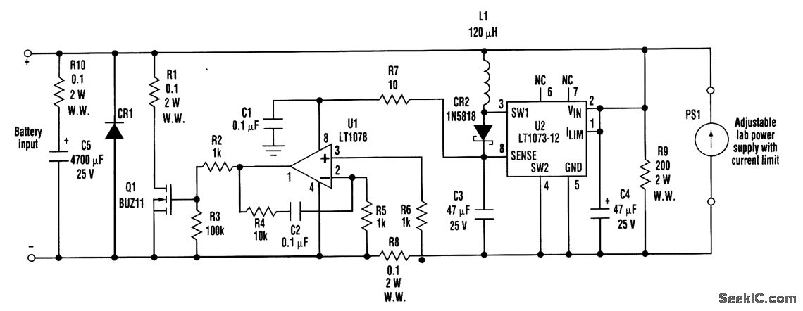
When developing a battery charger, using a real battery can be impractical. The battery simulator circuit described here serves as an alternative. The positive and negative terminals of the battery input should be connected in place of the actual...
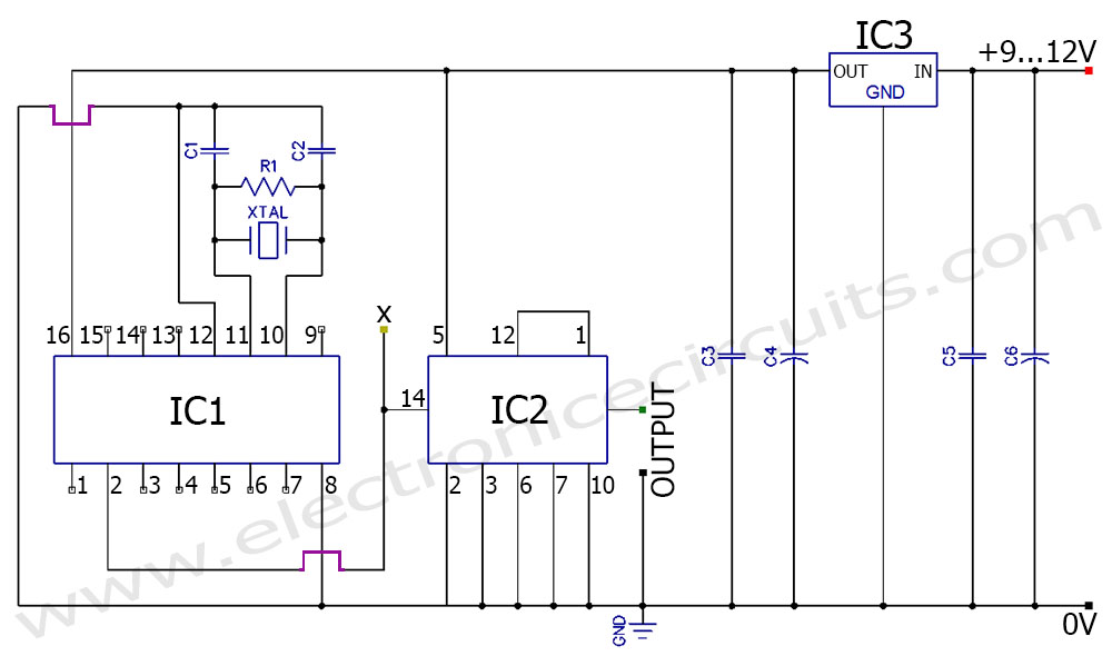
A frequency generator circuit capable of producing 50 Hz and 60 Hz outputs using a crystal oscillator. This oscillator can be utilized to generate precise frequency signals. This frequency generator circuit employs a crystal oscillator as its core component, which...
A relay (RL1) is activated with a 100-second delay when a +12V power supply is connected to the circuit. Figure 2 illustrates a relay timer circuit utilizing a 555 timer, featuring two time ranges: 6-60 seconds and 1-10 minutes...
This circuit is an enhanced Hartley oscillator, which allows for frequency adjustment within a specified range by altering the base current. The output signal amplitude exceeds 6V when tested with a 6kΩ load resistance, making it suitable for use...