
fading red eyes

The schematic diagram illustrates the layout of the circuit on a solderless breadboard, organized in rows labeled A-J and columns numbered 1 to 65. Each group of five holes in the same column are interconnected, meaning holes A1, B1, C1, D1, and E1 share the same connection, as do F1, G1, H1, I1, and J1. The outer rows along the board's length are typically used for power supply connections; however, there is a break in the midsection of these rows. A short jumper wire should be installed to connect the outer rows entirely. Familiarization with the board layout can be achieved using a digital multimeter (DMM) in the low ohms range to probe various holes. The LM1458 IC should be oriented such that the notch or punch mark on one edge is positioned near column 30, with the opposite edge near column 33. The LM1458 is installed on the breadboard with its pins straddling the center section, placing pin 1 in hole E30 and pin 8 in hole F30. The pins are numbered counterclockwise, positioning pin 4 in F33 and pin 5 in E33. Possible connections for the LM1458, a 9-volt battery, and additional components are depicted in the lower drawing of the solderless breadboard, although it may not include all parts. The schematic diagram should be referenced to ensure proper installation of the components, connecting them to the appropriate pins of the LM1458. While some components may fit conveniently, others may require short jumper wires (preferably #22 gauge) to connect parts across the IC. For instance, the 22µF capacitor connects between pins 1 and 2 of the IC, which occupy holes (F30, F31), but it could also be placed in holes (H30, H31) or (J30, J31) as needed.This circuit is used to slowly illuminate and fade a pair of red LEDs (light emitting diodes). The fading LEDs could be installed as `eyes` in a small pumpkin or skull as a Halloween attraction, or mounted in a Christmas tree ornament. Or, they might be used as a fancy power indicator for your computer, microwave oven, stereo system, TV, or other
appliance. In operation, a linear 3 volt (peak to peak) ramping waveform is generated at pin 1 of the LM1458 IC and buffered with an emitter follower transistor stage. The 22uF capacitor and 47K resistor connected to pin 2 establish the frequency which is about 0. 5 Hz. You can make the rate adjustable by using a 100K potentiometer in place of the 47K resistor at pin 2.
The circuit consists of two operational amplifiers (opamps), one producing a slow rising and falling voltage from about 3 volts to 6 volts, and the other (on the right) is used as a voltage comparator, the output of which supplies a alternating voltage switching between 2 and 7 volts to charge and discharge the capacitor with a constant current. Each of the op-amps has one of the inputs (pins 3 and 6) tied to a fixed voltage established by two 47K resistors so that the reference is half the supply voltage or 4.
5 volts. The left opamp is connected as an inverting amplifier with a capacitor placed between the output (pin 1) and the inverting input (pin 2). The right opamp is connected as a voltage comparator so that the output on pin 7 will be low when the input is below the reference and high when the input is higher than the reference.
A 100K resistor is connected between the comparator output and input to provide positive feedback and pulls the input above or below the switching point when the threshold is reached. When the comparator output changes at pin 7, the direction of the current changes through the capacitor which in turn causes the inverting opamp to move in the opposite direction.
This yields a linear ramping waveform or triangle waveform at pin 1 of the inverting opamp. It is always moving slowly up or down, so that the voltage on the non-inverting input stays constant at 4. 5 volts. Adjustments to the point where the LEDs extinguish can be made by altering the resistor value at pin 3 and 6 to ground.
I found a 56K in place of the 47k shown worked a little better with the particular LEDs used. You can experiment with this value to get the desired effect. Note: The LED listed has a narrow viewing angle of 30 degrees and appears brightest when looking directly at it. It`s not a pure red color, and a little on the orange side, but should be brighter compared to other selections.
For a wider viewing angle at reduced intensity, try part number 670-1257 which is viewable at 60 degrees and has a red diffused lens. Refer to the drawing below the schematic diagram and note the solderless breadboard is arranged in rows labeled A-J, and columns numbered 1 to 65.
Each group of 5 holes in the same column are the same connection, so that holes A1, B1, C1, D1 and E1 are all connected together. Likewise holes F1, G1, H1, I1 and J1 are all the same connection. The outer rows along the length of the board are also connected together and are normally used for power supply connections.
However, there is a break in the mid section of the outer rows, so a short jumper wire connecting the mid section of the outer rows should be installed to connect the entire outer row together. If you have a DMM, use the low ohms range and probe the various holes to get familiar with the board layout.
Orientate the LM1458 so the nook or punch mark on one edge is near column 30 and the opposite edge is near column 33. Install the LM1458 on the breadboard so the pins straddle the center section of the board and pin 1 of the IC is occupying hole E30 and pin 8 is in hole F30.
The pins are numbered counter clockwise, so pin 4 will be occupying F33 and pin 5 will be in E33. Possible connections for the LM1458, 9 volt battery, and a couple other parts is illustrated in the lower drawing of the solderless breadboard, but it is not complete with all parts. Refer to the schematic diagram, and install the various other components so they connect to the appropriate pins of the LM1458.
Use whatever connection holes are convenient. For example, the 22uF capacitor connects between pins 1 and 2 of the IC, which occupy holes (F30, F31) so it could be placed in the holes (H30, H31) or (J30, J31) or (I30, I31). But not all parts will conveniently fit, so you may have to use a short jumper wire (#22 preferred) to connect parts from one side of the chip to the other.
🔗 External reference
Related Circuits

The sensor/monitor depicted in the diagram activates the host system upon detecting infrared (IR) signals. It consumes very little supply current, allowing it to remain continuously operational in devices such as notebook computers or PDAs. The ultra-low current drain,...
This circuit is a simple IR detector for testing IR remote controllers. The circuit is based on one phototransistor which receives the IR beam. The NPN transistor works as an amplifier which feeds current to the LED. When this...
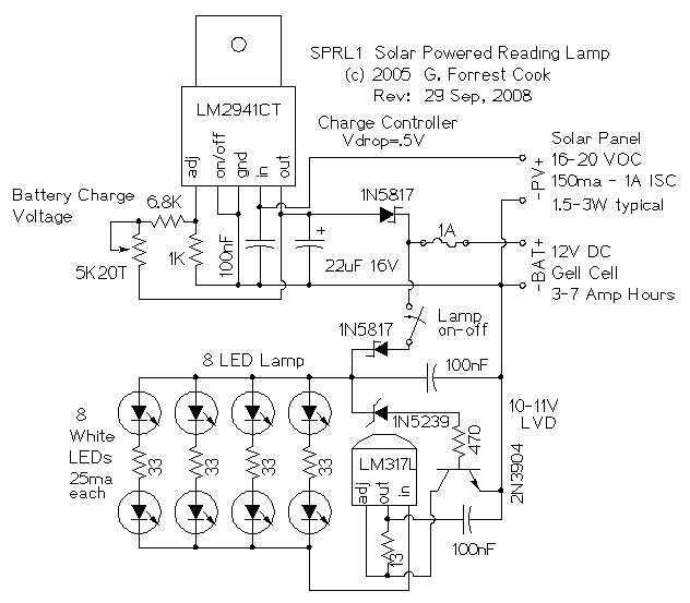
The reading lamp consists of a small solar panel, a standard UPS style lead acid battery, and an LED circuit board. The circuit board contains a low power solar charge controller (regulator), a set of 8 white LEDs, a...
This discussion assists in selecting the most appropriate microprocessor supervisor integrated circuit (IC) for specific applications and provides solutions for various common supervisory issues encountered with microprocessors. Microprocessor supervisor ICs are critical components in ensuring the reliable operation of microprocessor-based...

This circuit conducts a rapid battery test without requiring an external power supply or costly moving-coil voltmeters. It offers two testing ranges: when switch SW1 is configured as indicated in the circuit diagram, it can evaluate batteries ranging from...
Most homes today have at least a few infrared remote controls, whether for the television, video recorder, stereo, or other devices. Despite this, many individuals have experienced frustration when a light remains on after settling into a comfortable chair...