
Self-Powered Fast Battery Tester Schematic

This circuit design efficiently tests battery performance across a range of voltages, utilizing a combination of transistors, integrated circuits, and passive components to create a reliable testing mechanism. The use of FET Q1 as a constant current source ensures that the testing conditions remain stable regardless of the battery's initial voltage. This is critical for obtaining accurate readings during the test. The square wave generator (IC1) plays a pivotal role in producing a consistent oscillation that drives the inverter (IC2), which in turn controls the voltage multiplication process through the series of diodes and capacitors.
The LED indicators provide visual feedback regarding the battery's condition. LED D1 indicates the operational status of the circuit, while LED D7 serves as a warning indicator for under-voltage conditions. The design intelligently incorporates a voltage divider (R8-R10) to ensure that the biasing of Q3 is responsive to the battery's voltage level, allowing for a nuanced response to different battery states.
For the 1.5V battery testing configuration, the circuit adapts by applying a higher current load through the 10-ohm resistor, which compensates for the lower voltage range and ensures that the testing conditions remain effective. The inclusion of switches SW1A and SW1B allows for user-friendly operation, enabling quick adjustments to the testing parameters without complex reconfiguration.
Overall, this circuit represents a practical solution for battery testing, combining efficiency, cost-effectiveness, and ease of use, making it suitable for a variety of applications in both consumer and industrial settings.This circuit runs a fast battery test without the need of power supply or expensive moving-coil voltmeters. It features two ranges: when SW1 is set as shown in the circuit diagram, the device can test 3V to 15V batteries.
When SW1 is switched to the other position, only 1. 5V cells can be tested. FET Q1 provides a constant current generator biasing LED D1 and Q2 Base. In this manner D1 illuminates at a constant intensity, independent of battery voltage from 3 to 15V and Q2 (when P1 is closed) applies a constant current load of about 120mA to the battery. IC1 is a square wave generator oscillating at about 3KHz. IC2 acts as an inverter and drives, together with IC1 but in anti-phase, Diodes D2-D6 and Capacitors C4-C7, obtaining a voltage multiplication.
C8 is charged by this raised voltage and R8-R10 form a voltage divider biasing the Base of Q3. When P1 is open, a very light load is applied to the battery under test and Q3 Base is biased in order to maintain LED D7 in the off state. Closing P1, a 120mA load is applied to the battery under test. If the battery is not fully charged, its output voltage starts reducing: when this voltage fall 0. 6V below the battery nominal voltage, Q3 Emitter becomes more negative than the Base, the transistor is hard biased and D7 illuminates.
Obviously, this state of affairs will last a few seconds: the time spent by C8 to reduce its initial voltage to the new one, proportional to the voltage of the loaded battery. If the battery under test is in a good charging state, its output voltage will not fall under a 120mA loading current, so LED D7 will stay off.
When testing 1. 5V batteries, the circuit formed by Q1, Q2, D1, and R1 & R2 does not work well at this supply voltage, so a 150mA load current is applied to the BUT by means of the 10 Ohm resistor R3 after switching SW1A. Q3 bias is also changed via SW1B. 🔗 External reference
Related Circuits

The CMOS 4001 consists of four independent two-input NOR gates. These gates are organized into two pairs. Gates 1 and 2 are connected to form a latching circuit. When the alarm is triggered, they will latch and activate the...
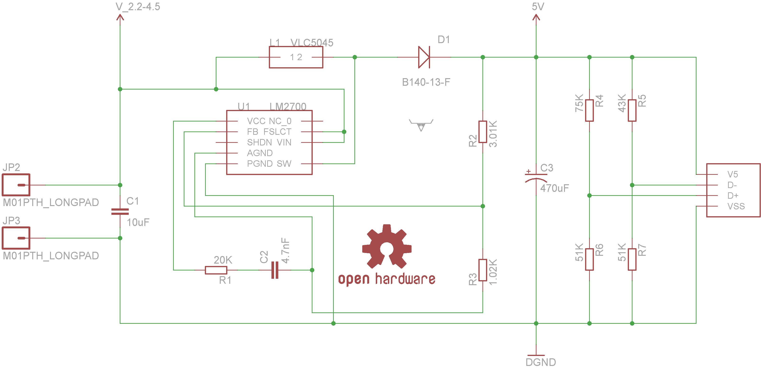
Powered by the LM2700 IC, this charger is capable of recharging devices such as MP3 players, cameras, cell phones, and any other gadgets that can be connected to a USB port at an accelerated rate. The circuit utilizes the LM2700...
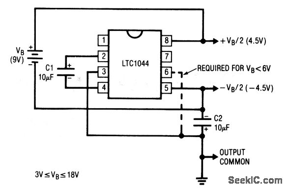
This circuit generates symmetrical ±output voltages, each equal to one-half of the input voltage (for example, a single 9-V battery). The output voltages are referenced to pin 3, which serves as the output common. The circuit is compatible with...
This is a simple NiCd battery charger powered by solar cells. A solar cell panel or an array of solar cells can charge a battery at more than 80% efficiency, provided the available voltage exceeds the fully charged battery...
This circuit falls under the category of an astable multivibrator. It is designed to test N-channel MOSFETs, specifically power types such as the IRF830, to determine their functionality. The astable multivibrator circuit is a type of oscillator that continuously switches...

This is a simple servo tester designed to thoroughly evaluate the capabilities of nearly any modern servo. It features two pushbuttons, labeled CENTRE and SWEEP, along with a potentiometer that functions in the following manner: The servo tester circuit is...