
Fake Car Alarm Circuit using 555 timer

The circuit utilizes a 555 timer IC configured in astable mode to produce a square wave output, which drives a red LED to flash periodically. The frequency of the flashing can be adjusted by changing the resistor and capacitor values connected to the timer.
The basic components of the circuit include the 555 timer IC, a red LED, a resistor, and a capacitor. The LED is connected to the output pin of the 555 timer, while the resistor and capacitor are connected to the discharge and threshold pins, respectively. The values of these components determine the timing characteristics of the flashing LED.
For instance, using a 1 kΩ resistor and a 10 µF capacitor will result in a flashing rate of approximately 0.1 Hz, meaning the LED will turn on for 5 seconds and then off for 5 seconds. This on/off cycle can effectively draw attention to the vehicle, deterring potential thieves.
The circuit can be powered by a 9V battery, providing a compact and portable solution for car protection. The simplicity of the design allows for easy assembly and troubleshooting, making it an accessible project for beginners.
To enhance the effectiveness of the deterrent, additional features such as a motion sensor or a sound alarm can be integrated, providing an even greater level of security. Overall, this simple 555 timer circuit serves as an effective and low-cost solution for vehicle protection against theft.This is a very simple 555 timer circuit,It make a simple theft detterant which may be just as effective. The idea is to have a flashing red led indicate that your car is protected. This device can protect your vehicle from potential thieves.. 🔗 External reference
Related Circuits
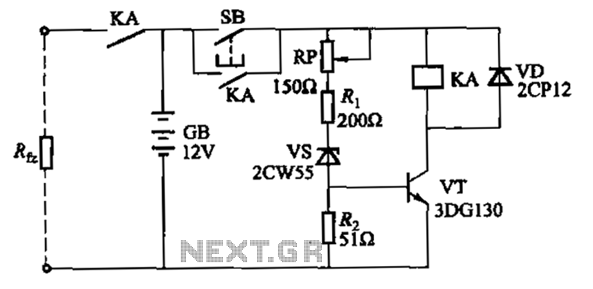
Deep discharge of a battery can lead to plate curing, which shortens the battery's lifespan. To prevent this, a discharge protection device can be implemented. The circuit diagram illustrates this mechanism. When the battery voltage falls to a predetermined...
The 555 timer on the right is configured as an alarm sound generator, while the second 555 timer on the left operates as a 1 Hz astable multivibrator. The output from the left timer modulates the frequency of the...
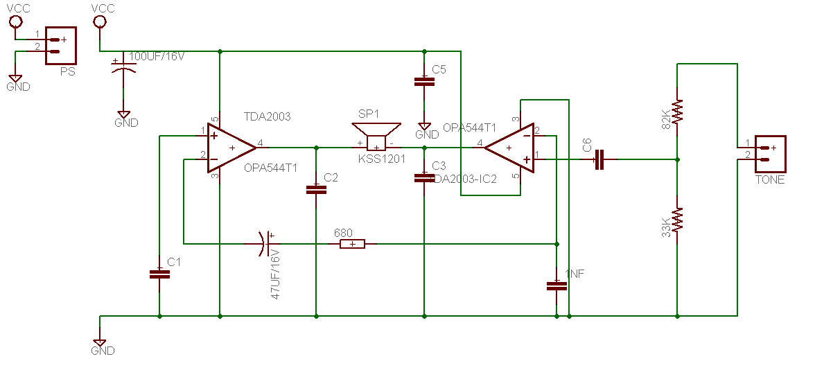
This is a design for a tone control circuit. The circuit features the LM1036, which is a DC-controlled tone (bass/treble), volume, and balance circuit suitable for stereo applications in car radios, televisions, and audio systems. The LM1036 integrated circuit is...
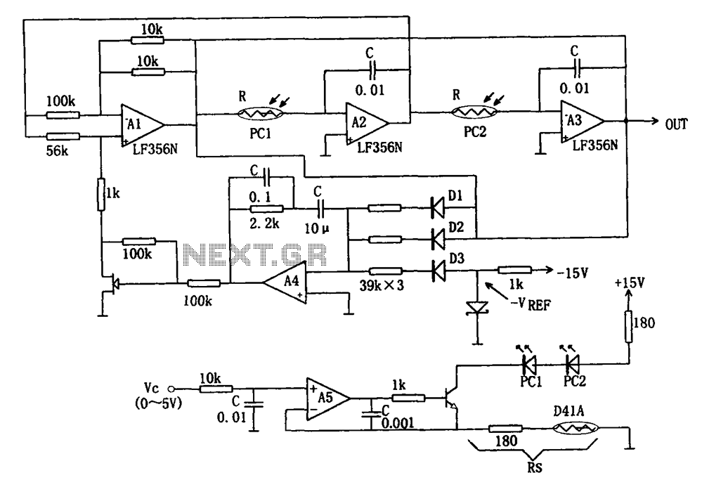
The wideband sinusoidal voltage-controlled oscillator circuit is designed such that the oscillation frequency is determined by an integrating resistor R and a capacitor C. The voltage-controlled oscillator is constituted by the applied control voltage Vc and a control resistor...
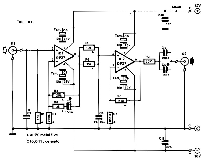
Circuit IC1 provides a gain amplification of 40 dB, which decreases to approximately 20 dB when the frequency exceeds 500 Hz. To reduce resistor noise and the load on the operational amplifier at higher frequencies, the value of resistor...
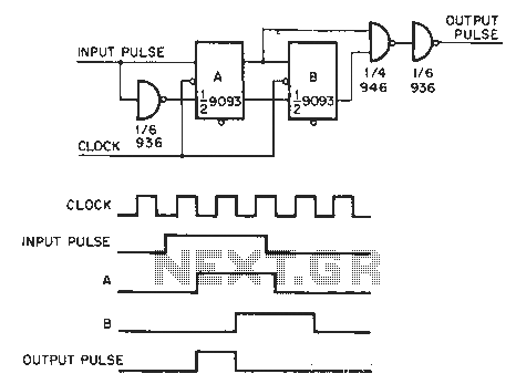
The circuit generates a clock that is synchronized with the pulse width of two clock pulses, producing a random pulse width that is five times the input pulse width of the clock pulse. In the flip-flop circuit, A and...