
Preamplifier for magnetic phono cartridges schematics

The circuit described consists of two primary amplification stages. The first stage, represented by IC1, operates as a low-noise preamplifier designed to amplify weak signals from a dynamic pick-up. The initial gain of 40 dB allows for effective amplification of low-level signals, which is critical in applications such as audio processing where signal integrity is paramount. The gain reduction to 20 dB at frequencies above 500 Hz indicates a frequency response tailored to minimize noise while maintaining signal fidelity at lower frequencies.
Resistor R3 plays a crucial role in this configuration. Its value is selected to strike a balance between minimizing thermal noise, which can adversely affect signal quality, and ensuring that the operational amplifier (op-amp) does not experience excessive loading at higher frequencies. This careful consideration of resistor value is vital for maintaining the overall performance of the circuit.
Capacitor C2, a polystyrene type, is specified with a tolerance of 1 to 2%. This precision is important in audio applications where variations in capacitance can lead to shifts in frequency response and signal distortion. The choice of polystyrene capacitors is often due to their favorable characteristics, including low dielectric absorption and low noise, which contribute to the high performance of the circuit.
The second stage of the circuit involves IC2, a linear amplifier designed to further boost the output signal from the dynamic pick-up. With a gain of 22 dB, this stage is capable of elevating the output to a more usable level, specifically targeting a line level of 250 mV at 1 kHz. This is particularly important for interfacing with subsequent audio processing equipment, ensuring compatibility and optimal signal levels.
Overall, this circuit design effectively amplifies low-level signals while managing noise and frequency response characteristics, making it suitable for high-fidelity audio applications. The combination of a well-chosen resistor value, a precision capacitor, and a robust linear amplifier stage results in a reliable and high-performance amplification solution.Circuit IC1 provides a do amplification of 40 dB, which drops to about 20 dB when the frequency rises above 500 Hz. To minimize the (resistor) noise and the load of the op amp at higher frequencies, the value of R3 is a compromise.
The associated polystyrene capacitor, C2, should have a tolerance of 1 to 2%. To raise the 2-mV output of the dynamic pick-up to line level at 1 kHz, linear amplifier IC2 has been added. This stage has a gain of 22 dB, so a signal of 250 mV is available at its output. 🔗 External reference
Related Circuits
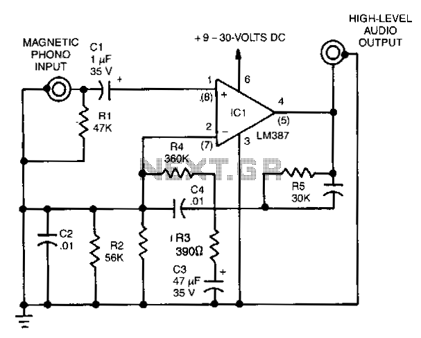
This simple stereo amplifier utilizes a National LM3871C. The pin numbers in parentheses correspond to one channel, while those without parentheses refer to the other channel. The supply voltage can range from +9 to +30 Vdc at approximately 10...
The circuit utilizes two 2N3819 FETs arranged in a cascode configuration. The lower FET functions in common source mode, while the upper FET operates in common gate mode, achieving full high-frequency gain. The lower FET is adjustable, enabling tuning...
The Audio Research Corporation LS22 Line Stage Preamplifier was selected for this upgrade. The Audio Research LS22 Line Stage Preamplifier is a high-performance audio component designed to enhance the quality of sound reproduction in audio systems. This preamplifier features a...
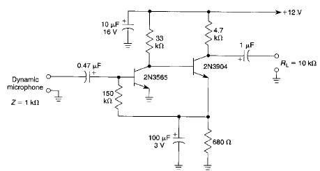
This microphone preamplifier electronic project is based on transistors and is capable of approximately 70 dB or more gain at audio frequencies. The gain of this circuit is roughly equal to the product of the hfe (current gain) of...
The circuit uses one simple, but effective power supply, which is sufficiently shielded by the rest of the circuit, if necessary, with aluminium to prevent noise. The entire circuit can be housed in a small box, from which only...
When there is a need to amplify audio signals from various sources before they reach a custom amplifier, a preamplifier (or preamp) is typically employed. This document suggests a specific circuit that is interesting due to its use of...