
FAN5607 Evaluation Board
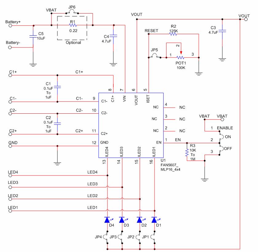
The FAN5607 Evaluation Board serves as a practical platform for evaluating the performance of the FAN5607 high-performance LED driver. The circuit is designed to efficiently drive multiple LEDs while maintaining a consistent current output, which is crucial for achieving uniform brightness and color consistency across the LEDs.
The core component, the FAN5607, is a high-frequency PWM (Pulse Width Modulation) driver that operates with a wide input voltage range, making it suitable for various applications. The 4x4 MLP package allows for a compact design, which is beneficial for space-constrained applications. The inclusion of two 4.7 µF capacitors is essential for stabilizing the input and output currents, ensuring that the driver can respond effectively to changes in load conditions without introducing flicker or fluctuations in brightness.
In addition to the LED driving capabilities, the evaluation board may include test points for measuring voltage and current, as well as jumper settings for configuring different operating modes. This flexibility allows engineers to explore various configurations and optimize the performance of the FAN5607 in their specific applications.
Overall, the FAN5607 Evaluation Board is an essential tool for designers looking to implement high-efficiency LED lighting solutions, providing a reliable means of assessing the capabilities of the FAN5607 driver in real-world scenarios.The FAN5607 Evaluation Board is a compact circuit including the FAN5607 HMPX in a 4x4 MLP package and two 4.7uF capacitors which can provide stable input/output current for up to four of Fairchild s super bright white LEDs. 🔗 External reference
Related Circuits
U1 is a Complex Interface Adapter (CIA). Both parallel ports are utilized to decode the keyswitches on the keyboard. Parallel port A signals (PA0 - PA7) function as outputs, while parallel port B signals (PB0 - PB7) serve as...
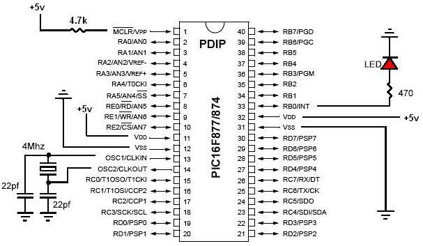
PIC development/testing board. This is a PCB design for a basic PIC16F877 development board. All that is required is a 4 MHz crystal, two 22 pF capacitors, and one 4.7 kΩ resistor. The PIC16F877 development board is designed to facilitate...
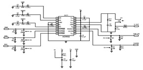
This schematic was created using a 2-layer evaluation board for the AD9662 3-Channel Laser Diode Driver. This device is primarily utilized in high-performance CD-DVD recordable drives and for laser diode current switching. The AD9662 is a specialized integrated circuit designed...
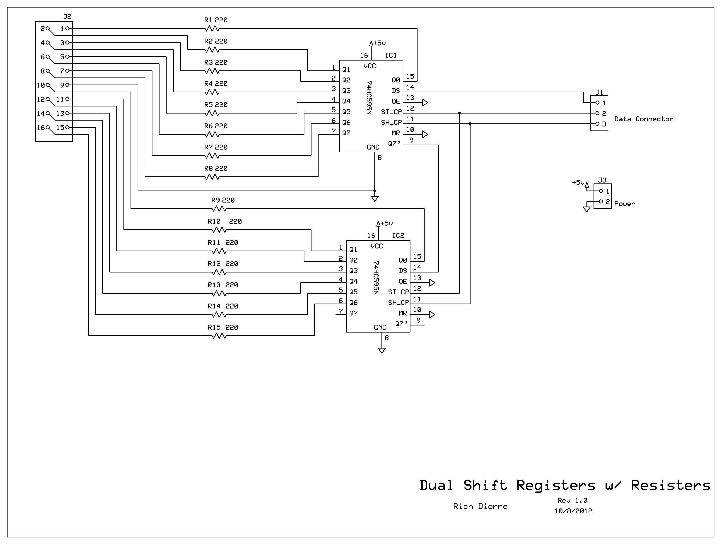
Control the two digits representing minutes; this circuit includes two shift registers, 30 resistors, and 30 LEDs. The schematic illustrates the design. As the circuit design neared completion, it became evident that soldering all components onto a basic prototyping...
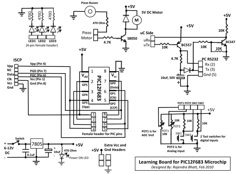
This microcontroller fascinated me a lot because I wanted to see what we can do with an 8-pin microcontroller (out of which 2 pins goes to power supply, so actually just 6-pins are left for I/O). So I thought...

Battery vampires are circuits designed to extract as much energy as possible from batteries or cells. They are not regulated drivers; rather, they are boost circuits that create a higher output voltage from a low input voltage and provide...
Warning: include(partials/cookie-banner.php): Failed to open stream: Permission denied in /var/www/html/nextgr/view-circuit.php on line 713
Warning: include(): Failed opening 'partials/cookie-banner.php' for inclusion (include_path='.:/usr/share/php') in /var/www/html/nextgr/view-circuit.php on line 713