
Fast Video Signal Amplitude Measurer Circuit

The circuit operates by capturing the peak amplitude of the video signal, which is essential in various applications such as video processing and display calibration. The high-speed buffer (U1) ensures that the incoming video signal is accurately transmitted to the comparator (U2) without significant delay or distortion. This is crucial for maintaining the integrity of the signal being measured.
The latched comparator (U2) compares the incoming signal with a reference level and latches its output state, thus providing a stable reading of the peak amplitude. The hold capacitor (C1) retains the measured voltage, allowing for a consistent output that reflects the maximum amplitude of the video signal over time. This feature is particularly useful when analyzing rapid changes in video signal amplitudes, as it allows for a snapshot of the peak value.
The reset mechanism, controlled by transistor Q3, is vital for ensuring that the system can accurately measure new peaks without interference from previously captured values. During a reset operation, Q3 pulls the comparator output low, clearing the previous state and preparing the circuit for the next measurement cycle.
Overall, this circuit design is effective for applications requiring precise measurement of video signal amplitudes, ensuring reliable performance in various electronic systems that utilize RGB signals from video RAMDACs. Video-signal amplitude can be measured with this simple circuit, which is basically a modified standard peak detector. The device can verify RGB generated by video RAMDACs. Ul is a high-speed buffer and U2 is a latched comparator. CI is a hold capacitor. Reset is performed by Q3. U2 has a latch that maintains the last comparator state. The reset holds the comparator output low during the reset operation. The dc output voltage is equal to the signal`s maximum amplitude.
Related Circuits
If a negative supply is required for an operational amplifier or if a negative bias voltage is needed while operating from a single supply voltage, such as in battery applications. To generate a negative supply voltage from a single positive...
This circuit is constructed using two LT1001 operational amplifiers (OP-AMPs), with the output of the OP-AMP saturating at +5V. The power supplies used are +5V and ground. According to the documentation, applying +1V to the "Servo Input" results in...
A platform for sharing and discovering articles and documents. Users can upload their knowledge, share it with others, or search through the database to find relevant articles. This platform serves as a collaborative space where individuals can contribute their expertise...

The LT1007 is capable of providing excitation current directly to bias the 350-0 bridge at 5 V. With only 5 V across the bridge, as opposed to the usual 10 V, total power dissipation and bridge warm-up drift is...
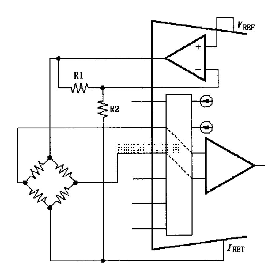
The circuit voltage source VREF excites the sensor bridge. The excitation voltage VEX is defined as VREF (1 + R1/R2), where the bridge is connected at both ends. The sensor bridge circuit is designed to convert a physical quantity, such...
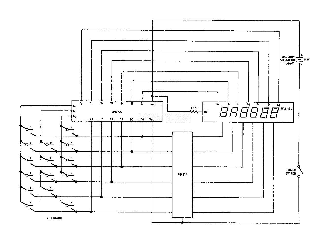
Configure the National Semiconductor DS8877 drive circuit as shown. When used with a 6-digit calculator and digital current conjunction, the current range is from 5 to 50 mA. The drive does not require standby power, and the operating voltage...