
XTR108 VREF driven by the excitation circuit diagram of the bridge

The sensor bridge circuit is designed to convert a physical quantity, such as pressure or temperature, into a measurable electrical signal. The voltage source VREF serves as the reference excitation voltage for the sensor bridge, ensuring accurate and stable operation. The excitation voltage VEX is derived from VREF, adjusted by the ratio of resistors R1 and R2, which can be used to calibrate the bridge output for specific applications.
In this configuration, the sensor bridge typically consists of four resistive elements arranged in a Wheatstone bridge configuration. The output voltage from the bridge is proportional to the differential resistance change caused by the physical stimulus. The excitation voltage VEX is critical as it directly influences the sensitivity and linearity of the sensor's response.
To achieve optimal performance, careful selection of the resistors R1 and R2 is necessary. These resistors can be chosen based on the desired gain and sensitivity of the bridge output. The ratio R1/R2 allows for fine-tuning of the excitation voltage, which can help in compensating for temperature variations and other environmental factors that may affect sensor readings.
In practical applications, the output from the sensor bridge can be connected to an amplifier circuit to enhance the signal for further processing. This amplified signal can then be interfaced with an analog-to-digital converter (ADC) for digital processing, enabling integration with microcontrollers or digital signal processors for data analysis and monitoring.
Overall, the design and implementation of the excitation voltage source and the sensor bridge are crucial for achieving accurate and reliable measurements in various electronic sensing applications. As shown, the circuit voltage source VREF excitations sensor bridge. This is a very good incentives, the excitation voltage VEX VREF (1 + R1/R2), wherein both ends of the bridg e VEX is the excitation voltage.
Related Circuits
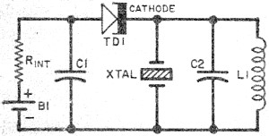
Leo Esaki invented the tunnel diode in 1957 while working at Sony (then known as Tokyo Tsushin Kogyo). Tunnel diodes feature a very narrow, heavily doped p-n junction approximately 10 nm wide, which exhibits a broken bandgap. This configuration...

This is a design circuit for a soft light dimmer. The circuit utilizes the IGBT STGP10N50A and the TS555 timer as the main components. The timer is triggered by the zero crossing voltage pulse. The time constant, determined by...
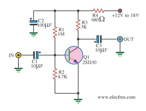
When there is a need to amplify audio signals from various sources before they reach a custom amplifier, a preamplifier (or preamp) is typically employed. This document suggests a specific circuit that is interesting due to its use of...

This circuit generates the power required to operate a bipolar stepper motor. It allows for adjustments in both the rotation speed and direction of the motor. The design includes two integrator circuits (A1, A3) and an amplifier (A2) connected...

The following circuit illustrates a 35W quadruple amplifier and a 2 x 25W bridge amplifier based on the TDA7375 integrated circuit (IC). This circuit requires a minimal number of external components. Although initially designed for car applications, it can...
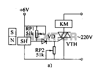
The automatic weapon features a magnetic switch circuit that is simple, reliable, has a low failure rate, and offers good versatility. It can be used for output performance or converted into mechanical displacement applications. The circuit diagram utilizes a...