
FET Preamplifier Circuit

The Field Effect Transistor (FET) operates by utilizing an electric field to control the flow of current. In this configuration, the input voltage applied to the gate terminal modulates the conductivity of a channel, allowing for amplification of signals. The FET preamplifier is particularly effective in low-level signal applications due to its high input impedance and low output impedance, which minimizes loading effects on the preceding stage of the circuit.
In a typical FET preamplifier circuit, the FET is connected in a common-source configuration, where the source terminal is grounded. The input signal is applied to the gate, and the amplified output is taken from the drain terminal. Biasing resistors are employed to set the operating point of the FET, ensuring linear amplification over the desired range of input signals. Coupling capacitors may also be used to block DC components while allowing AC signals to pass through.
The sensitivity of the FET preamplifier allows it to effectively amplify small signals, such as those from sensors or microphones, making it suitable for various applications in audio processing, instrumentation, and communication systems. The design considerations for the FET preamplifier include selecting an appropriate FET type, determining the biasing resistors' values, and ensuring proper power supply decoupling to maintain stability and performance.Field Effect Transistor is an amplifying device in which the output current depends on the input voltage. The FET Pre Amplifier described here is a sensiti.. 🔗 External reference
Related Circuits
Comprehensive information regarding the RF Field Strength Meter Circuit is available. Users can learn about and download the RF Field Strength Meter Circuit online. The RF Field Strength Meter Circuit is designed to measure the strength of radio frequency (RF)...
The PowerSaver Flasher uses capacitive output coupling to produce brighter shorter flashes and has a much lower average current drain than standard bicore or 74HC14 flashers. The PS Flasher with one LED circuit (2 LEDs) runs all night from...
This is a INA159 Dual-Polarity, Bidirectional Current-Shunt-Monitor Circuit. This circuit uses OPA340 because it has near rail-to-rail input and output swing. The INA159 is an integrated circuit designed for high precision current sensing applications. It is capable of measuring bidirectional...

This 555 timer circuit temperature monitoring system project can monitor temperature at up to four points. The system allows for the selection of whether the alarm should be triggered when the temperature increases or decreases, depending on the resistance...

This simple DC servo motor circuit design can be utilized in various electronic projects. The circuit schematic illustrates that this DC servo motor driver employs a single integrated circuit along with a few external electronic components. For bidirectional DC...
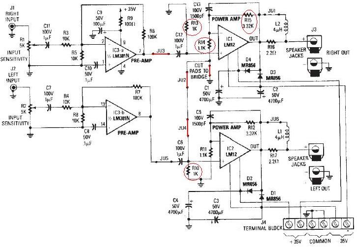
The LM12 audio amplifier circuit is designed to deliver high output power for 8 ohm or 4 ohm load impedances. The maximum output power provided by the LM12 audio amplifier is approximately 60 watts for a 4 ohm load...