
DC servo motor circuit design using A3952S motor driver

The described DC servo motor circuit is designed to control the motion of a servo motor efficiently. The core of the design is a single integrated circuit (IC), which simplifies the control mechanism while maintaining functionality. The IC typically serves as a driver, regulating the power supplied to the motor based on input signals.
In the schematic, the connections to the PHASE terminal are crucial for enabling bidirectional control of the motor. By adjusting the signal at this terminal, the direction of the motor's rotation can be reversed. This feature is particularly useful in applications requiring precise control over rotational direction, such as robotics or automated systems.
The circuit also incorporates several passive components, including resistors and capacitors, which serve to filter signals and stabilize the operation of the IC. These components help mitigate noise and ensure smooth transitions between different operational states of the motor.
When the motor experiences abrupt directional changes, it generates back EMF, which can lead to sudden spikes in current. The design must account for this phenomenon to protect the circuit and ensure reliable operation. The current generated by back EMF is influenced by the speed and load conditions of the motor, necessitating careful consideration during the design phase to avoid potential damage to the components.
Overall, this DC servo motor circuit is a versatile solution, suitable for a range of applications in electronic projects, providing effective control and reliability in motor operation.This simple DC servo motor circuit design that can be used in various electronic projects. As you can see in the circuit schematic this Dc servo motor driver schematic circuit use just one integrated circuit and other few external electronic components. With bidirectional dc servo motors, the PHASE terminal can be used for mechanical direction c ontrol. Similar to when braking the motor dynamically, abrupt changes in the direction of a rotating motor produce a current generated by the back EMF. The current generated will depend on the mode of operation. 🔗 External reference
Related Circuits
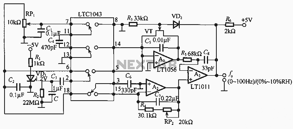
The humidity/frequency conversion circuit operates similarly to the previously mentioned humidity sensors. At a humidity level of 76%, the equivalent capacitance is 500 pF, with a capacitive relative humidity variation rate of +1.7 pF/%. The circuit includes an integrating...
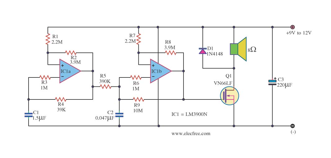
This circuit is a sound generator designed to create a super siren alarm signal using a live frequency generator circuit that incorporates an operational amplifier (op-amp). The circuit operates on the principle that when switch S1 is not pressed,...
To achieve a low-cost, accurate, and simple position control system, a stepper motor can be utilized. A circuit designed to drive the motor should be mounted in proximity to the motor itself. Stepper motors are widely employed in applications requiring...
The bi-directional sequencer utilizes a 4-bit binary up/down counter (CD4516) and two "1 of 8 line decoders" (74HC138 or 74HCT138) to create the well-known "Night Rider" display. A Schmitt Trigger oscillator generates the clock signal for the counter, with...
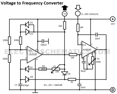
This voltage-to-frequency converter circuit features a voltage-controlled oscillator with a small deviation of 0.5%. The integrated circuit IC1 operates as a multivibrator. The voltage-to-frequency converter circuit is designed to convert an input voltage into a corresponding frequency output. The core...
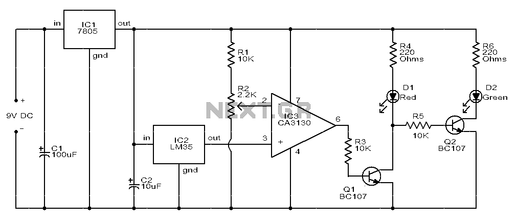
The circuit consists of two light-emitting diodes (D1 and D2) whose operation is controlled by the ambient temperature. A temperature sensor, the LM35, generates an output of 10 mV for each degree of temperature increase. A reference potentiometer, R2,...