
FET relay circuit 2

The FET relay circuit, designated as the JS-20 time relay, operates by utilizing a field-effect transistor (FET) as a control element to manage the timing function of the relay. The circuit is designed to maintain the relay in a deactivated state when the switch SA is open. This is achieved by ensuring that no current flows through the relay coil, thereby keeping the relay device KA in its released state.
Upon closing switch SA, the circuit initiates a delay sequence. During this delay, the capacitor in the timing circuit begins to charge through a resistor, forming an RC time constant that determines the duration of the delay. The time taken for the capacitor to charge to a specific voltage level is what ultimately dictates when the thyristor will be triggered.
Once the capacitor reaches the required voltage, the thyristor is activated, allowing current to flow through the relay coil. This activation pulls in relay KA, switching the connected load on. The delay time can be adjusted by varying the resistance of potentiometer RP, which alters the RC time constant. By increasing the resistance, the time delay increases, while decreasing it shortens the delay.
The circuit may also include additional components such as diodes for flyback protection to prevent voltage spikes when the relay coil is de-energized. Overall, this FET relay circuit provides a reliable and adjustable timing mechanism suitable for various applications where controlled delay activation is necessary.FET relay circuit 2 It is actually a JS-20 time relay circuit. SA before the switch is closed, the relay device KA tends to release state. After SA closed circuit delay start, after a period of time, the thyristor is turned on, KA pull. Adjustment potentiometer RP, can change the delay time.
Related Circuits
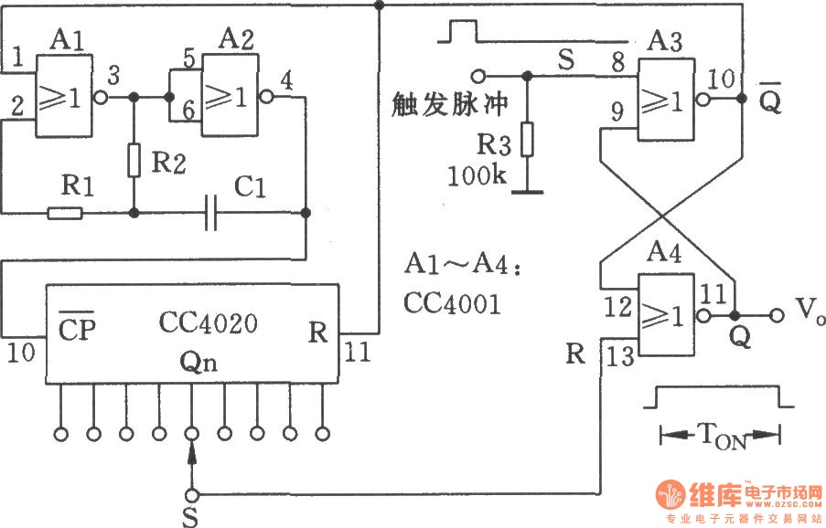
The NC monostable multivibrator circuit depicted in the chart consists of four 2-input NOR gates (CC4001) and a 14-bit binary serial counter/divider (CC4020). It is primarily utilized as a time delay switch or timer in automatic control equipment. The NC...
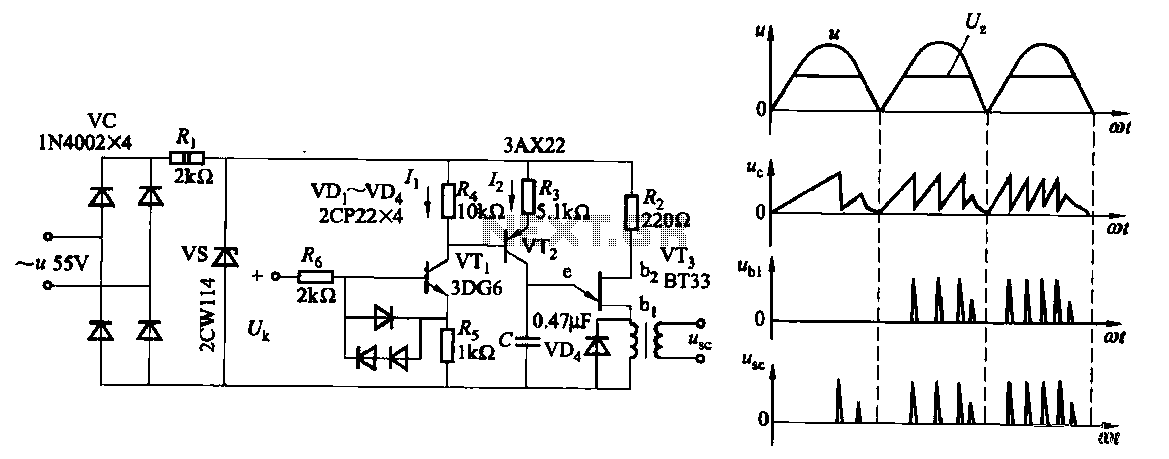
Due to the increased level of the transistor amplifier circuit, the control circuit's performance in Figure 16-6 is more sensitive and can accept input control signals superimposed on others (such as voltage, current, and speed feedback signals) to meet...
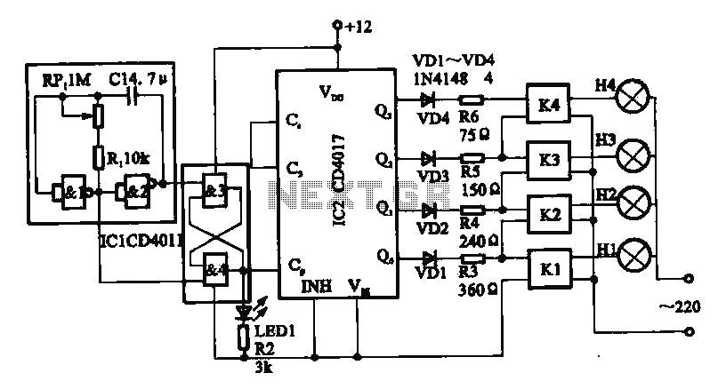
This circuit illustrates a circular lighting control system. It consists of four two-input NAND gates from the CD4011 series, which form a non-inverting multivibrator. This multivibrator generates a pulse that is used to shape the output of an RS...
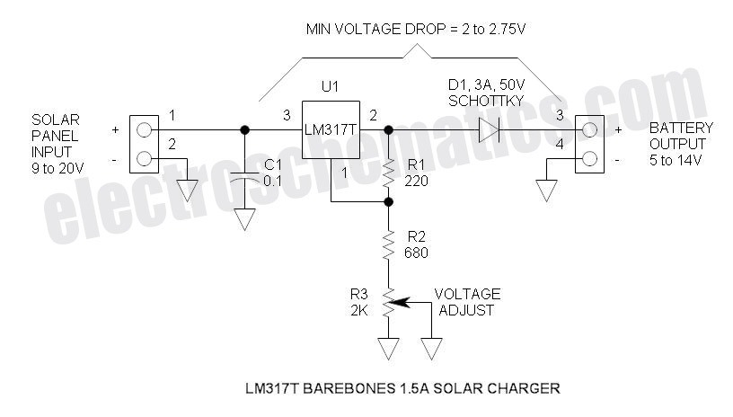
This solar battery charger is a simple and cost-effective project suitable for hobbyists. While it has some limitations compared to other similar devices, it offers several advantages. The charger is designed for lead-acid batteries but can also charge any...
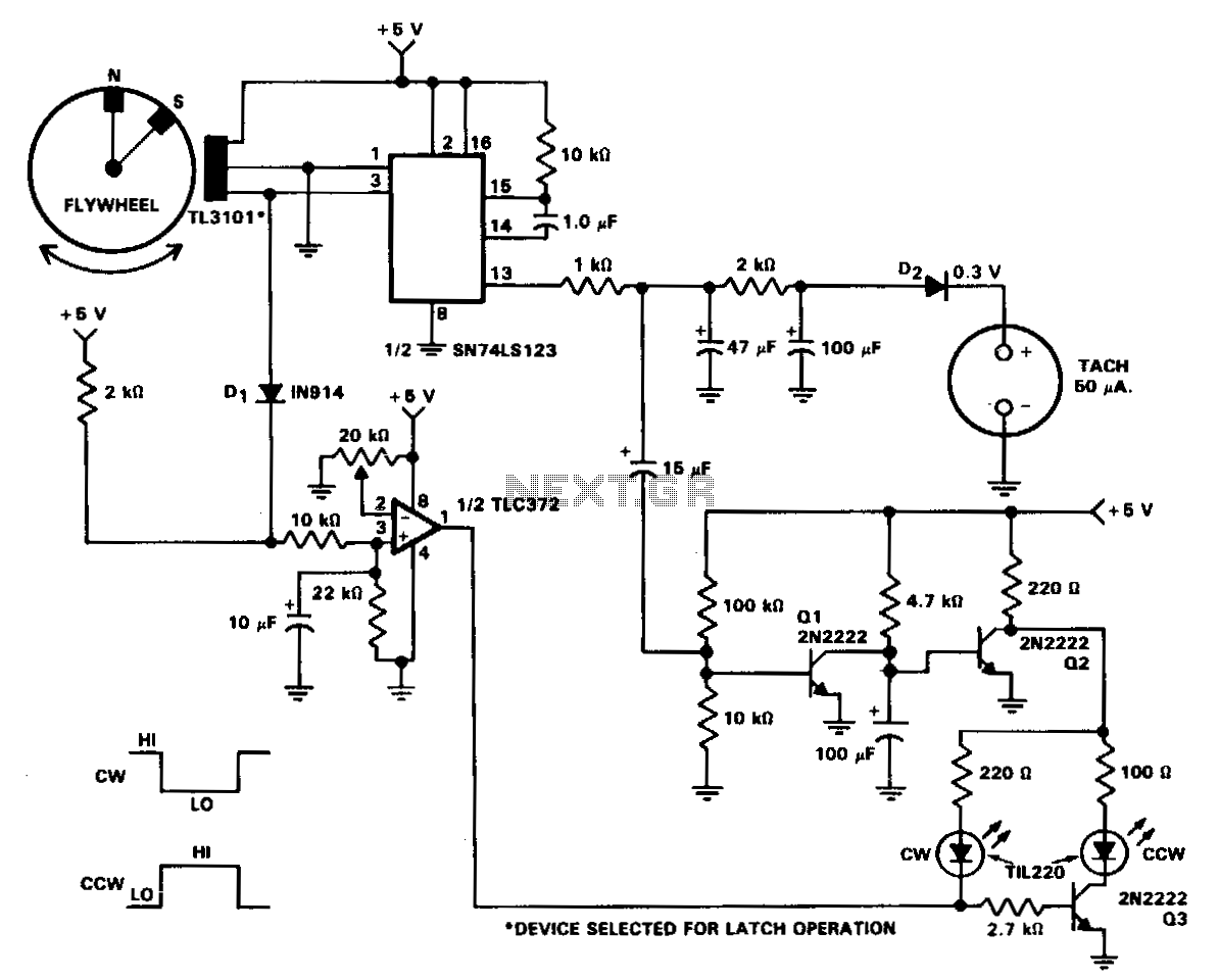
In machine and equipment design, certain applications necessitate the measurement of both shaft speed and direction of rotation. The circuit of a tachometer, which also indicates the direction of rotation, is illustrated. A flywheel is equipped with two magnets...
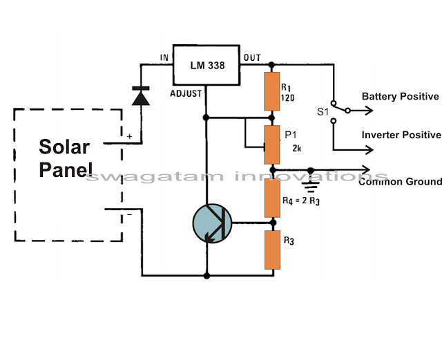
Solar panels are well-known devices that convert solar energy or sunlight into electricity. A solar panel consists of discrete sections of individual photovoltaic cells, each capable of generating a small amount of electrical power, typically between 1.5 to 3...