
Loop lighting control circuit

The circular lighting control circuit utilizes the CD4011 NAND gate IC to create a non-inverting multivibrator, which is essential for generating timed pulses. The multivibrator operates based on the feedback provided by the NAND gates, ensuring stable pulse generation. The output pulse from the multivibrator is fed into an RS flip-flop, which helps to maintain the state of the output until triggered by the next clock pulse.
The CD4017 IC functions as a decade counter, which counts the clock pulses it receives at its Cp input. Each time a pulse is received, the output advances to the next state, cycling through Q0 to Q3. This sequential output is crucial for controlling the solid-state relays, which act as switches for the lamps. The relays are designed to handle the load of the lamps, providing isolation and protection for the control circuitry.
The timing of the lamp sequence is adjustable via the variable resistor RP1. By changing the resistance, the time each lamp remains illuminated can be fine-tuned, allowing for flexibility in the lighting control system. This feature is particularly useful in applications where different lighting durations are required, such as in decorative lighting setups or for signaling purposes.
Overall, this circuit effectively demonstrates the integration of digital logic components to achieve a practical and functional lighting control system, showcasing the capabilities of the CD4011 and CD4017 ICs in creating a reliable and adjustable sequence of operations for lighting applications.It shows a circular lighting control circuit. Circuit, rCl of four two-input NAND gate CD4011, which made of a non- door l, 2 multivibrator composed by the NAND gate 3,4 RS flip-flop circuit consisting of a pulse generated by the multivibrator shaping, then the output of NAND gate 4 output from the clock pulse to the end of IC2 Cp. IC2 is a decimal counter / divider CD4017, when it Cp-ended input clock pulse, the output terminal Qo-Q3 will appear sequentially high -level pulse signal. When Qo-Q3 sequentially appear high, solid state relays Kl ~ K4 are sequentially turned on by the trigger, so that the corresponding lamp H1 ~ H4 is lit one by one.
The IC2 cleared again began this process in order to achieve the control function of the lamp light cycle. Circuit. Each sequence street lighting off time and full-time to stay the same, RP1 can adjust the time 0.1-10 s in the room changed.
Related Circuits
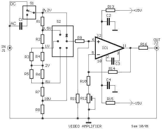
This is a schematic diagram of a video amplifier circuit, built using the very high-speed operational amplifier IC LH0032. Parts List: R1 = 15KΩ, R2, R3, R4 = 10KΩ, R5, R6, R7, R8, R9 = 1KΩ, R10 = 820Ω,...
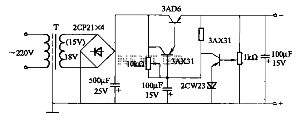
A power supply circuit designed to operate within a voltage range of 6 to 15V, providing a current output of 500mA. This circuit includes an adjustable amplification segment and utilizes a composite transistor configuration for its power supply. The described...
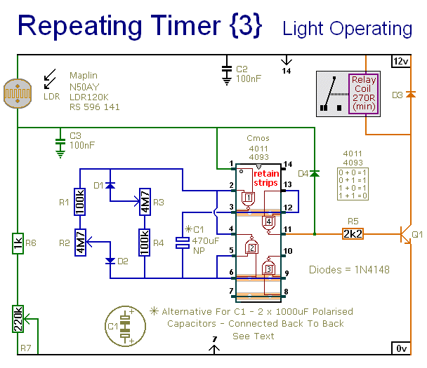
This circuit closely resembles Repeating Timer No. 2. However, the inclusion of a light-dependent resistor (LDR) allows the timer's operation to be confined to daylight hours. Resistor R7 enables the adjustment of the light level at which the timer...
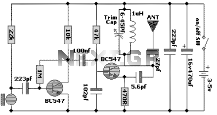
The following schematic diagram shows the design of a 100 MHz Radio Frequency RF Oscillator Circuit. The electrets microphone picks up and amplifies sound then fed it into the audio amplifier stage built around the first transistor. The output...
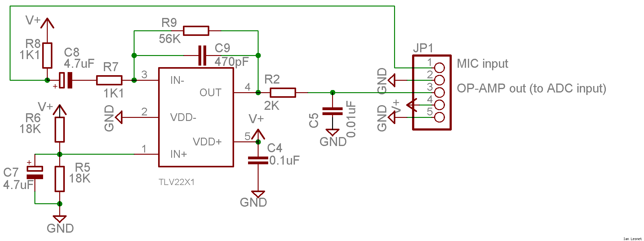
This project utilizes a small, common electret microphone to convert audio into an electrical signal. These inexpensive microphones are typically found in most PC headsets. The output from the microphone must be amplified and zeroed before it can be...
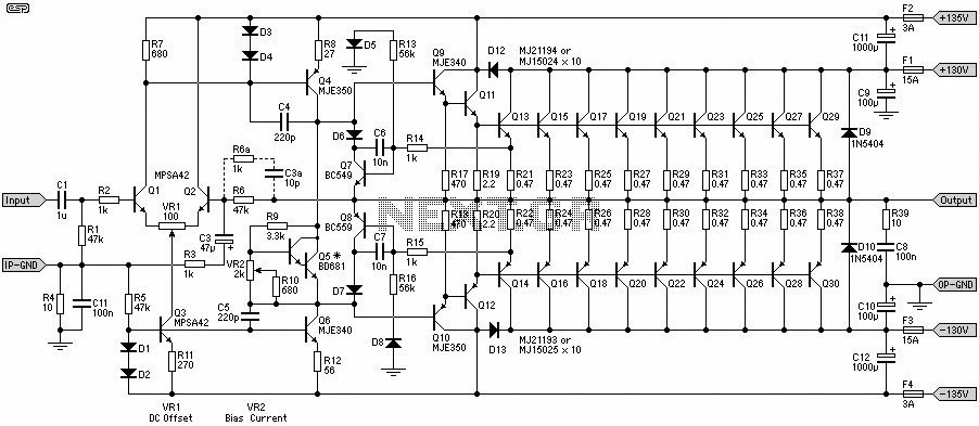
This 1500W Power Amplifier Circuit Diagram contains two images of the circuit. For more complete information, refer to the main post titled "1500 Watt Power Amplifier." It includes a list of component parts for the 1500W Power Amplifier Circuit...