
FET several basic bias circuit - self bias voltage divider circuit

The self-bias voltage divider circuit is a fundamental configuration used in Field Effect Transistor (FET) biasing. This circuit employs two resistors to create a stable bias voltage for the transistor's gate, ensuring consistent operation across varying conditions. The voltage divider consists of two resistors connected in series across a supply voltage, with the junction of the resistors providing the bias voltage to the FET gate.
In a typical configuration, the resistors R1 and R2 are connected from the supply voltage (Vcc) to ground. The voltage at the junction point, which is the gate of the FET, can be calculated using the voltage divider formula: Vg = Vcc * (R2 / (R1 + R2)). This configuration allows the gate voltage (Vg) to remain relatively stable despite variations in the FET's characteristics or supply voltage fluctuations.
The self-biasing feature is particularly advantageous as it allows for automatic adjustment of the gate voltage based on the drain-source voltage (Vds) and the transconductance (gm) of the FET. This results in improved linearity and reduced distortion in amplifier applications. Additionally, the choice of resistor values (R1 and R2) directly influences the bias point and the overall performance of the circuit, making it crucial to select appropriate resistor values based on the desired operating point of the FET.
Overall, the self-bias voltage divider circuit is an essential component in FET amplifier design, providing a reliable and efficient means of biasing that supports consistent performance across various operational conditions.FET several basic bias circuit - self bias voltage divider circuit
Related Circuits
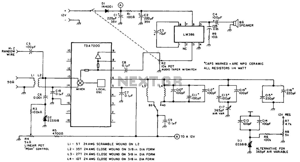
This direct-conversion receiver utilizes a TDA7000 integrated circuit (IC) and incorporates an LM386 audio amplifier. The TDA7000 serves as the mixer and local oscillator (L.O.) section. The frequency control can be achieved using either an air variable capacitor or...
The Electronic Cash Register (ECR) keeps track of sales transactions quickly and effectively. An abundance of PLUs (Price Look Ups) and department keys accommodate a variety of merchandise items. This means a faster, more accurate check out process and...
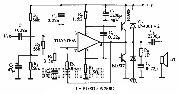
The rDA2030A TDA2030 is an enhanced version of the original product, with a maximum working voltage increased to 18V and a maximum output power of 18W. Additionally, harmonic distortion has been significantly reduced. The application circuit is illustrated. The rDA2030A...
This general-purpose amplifier has a bandwidth of approximately 20 MHz and it uses an LM733/NE592 video amplifier integrated circuit. This circuit can be utilized as a line driver or as a LAN line driver. The circuit employs the LM733/NE592 video...
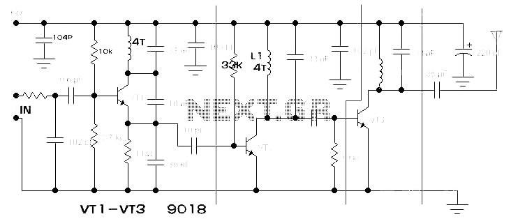
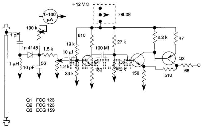
The components available were utilized to create a long-range FM radio transmitter operating within the 88-108 MHz band, designed for playing music. The circuit includes a power section that rectifies mains voltage to provide a stable 12V DC for...
Circuit diagram for a mini emergency lamp. This mini emergency lamp activates during power failures to provide cool white light in the room. It utilizes a 1-watt white LED to deliver adequate illumination. The circuit for the mini emergency lamp...