
FET VOLTMETER

The circuit utilizes the 2N3819 field-effect transistor (FET) in a cathode follower configuration, which is advantageous for its high input impedance and low output impedance characteristics. This makes it suitable for buffering signals without significant loading effects on the preceding stage. The FET operates in the linear region, allowing for accurate voltage tracking.
The bias offset is crucial for ensuring that the meter reads correctly at zero input. Resistors R14 and R12 are strategically chosen to set the quiescent point of the FET, allowing for precise adjustments to achieve the desired meter null. The values of R2 through R9 are selected to provide a combined resistance of approximately 10 MΩ, which is necessary for the full-scale calibration of the VOM. This ensures that the meter can accurately measure a wide range of voltages.
Resistor R10 serves a protective role in the circuit, safeguarding the FET from excessive current that could lead to damage. This is particularly important in applications where the input voltage may vary significantly. Additionally, capacitor C2 is included to provide AC bypassing, which effectively filters out high-frequency noise and RF interference that could affect the accuracy of the measurements. By ensuring a clean signal is presented to the FET, the overall performance and reliability of the voltage output meter are enhanced.
In summary, the 2N3819 FET-based VOM circuit is designed for high accuracy and stability in voltage measurements, incorporating essential components for calibration, protection, and noise reduction.A2N3819 FET provides a solid state VOM ‚The 2N3819 acts as a cathodefollowerin a VOM The biasoffset(meter null) is obtained with R14 and R12 sets full scale calibration R2 through R9 should totalabout10 M © R10 is a protective resistor and C2 provides ac bypassing to limit rf and noise pickup 🔗 External reference
Related Circuits
During DC analysis, all AC voltage sources are removed from the circuit since they are AC sources. DC analysis focuses solely on DC sources. Additionally, all capacitors are removed because, in a DC context, capacitors act as open circuits....
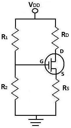
This is the FET amplifier circuit, which utilizes an FET transistor. The gate of the FET must be negative relative to the source to achieve proper biasing. The voltage across the source resistor is generated by the drain current...
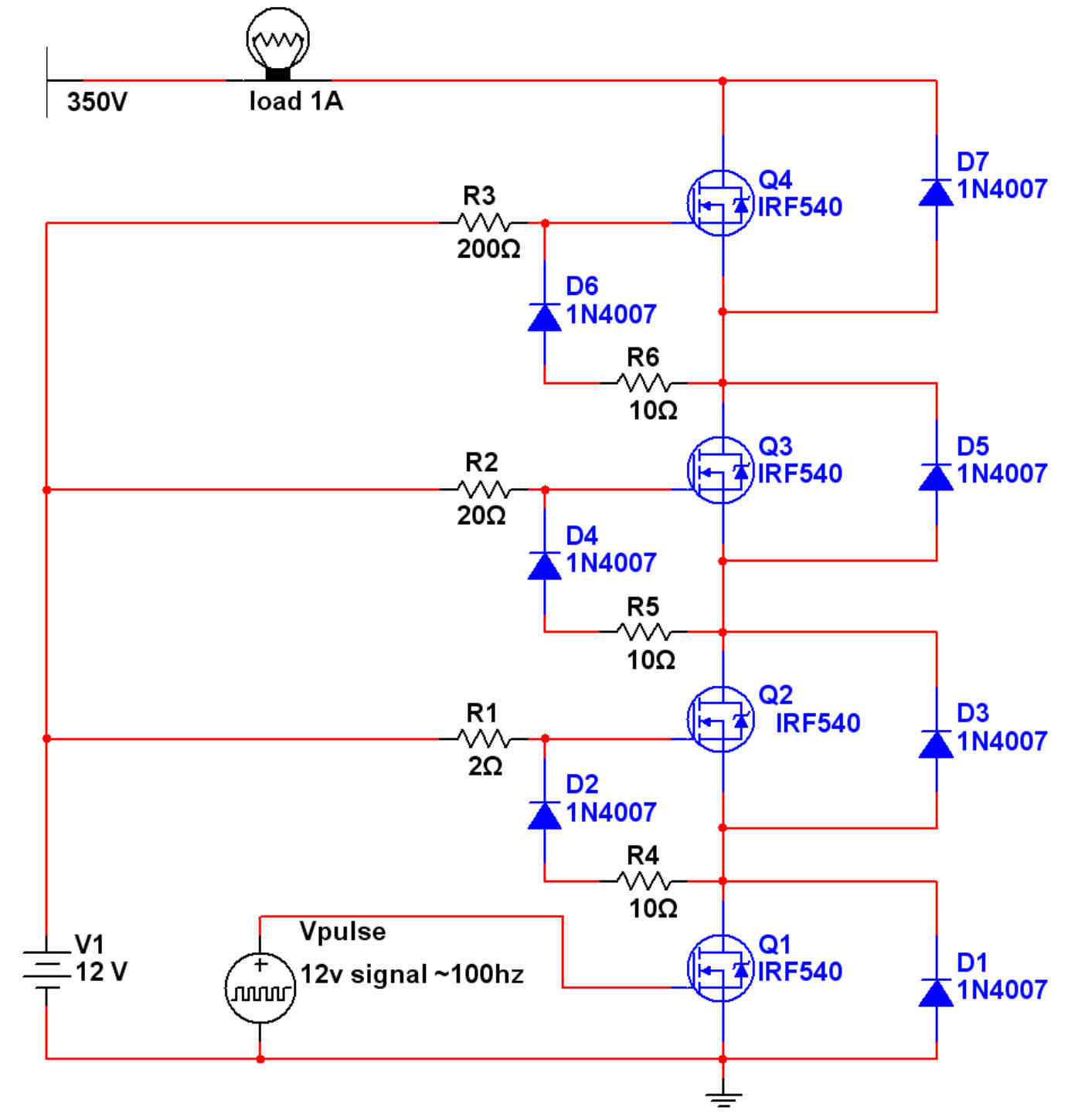
Some time ago, a document was encountered that explains how to wire MOSFETs in series to achieve higher voltages (pages 10-14). This is the only schematic found to be functional so far. However, an issue arises when attempting to...
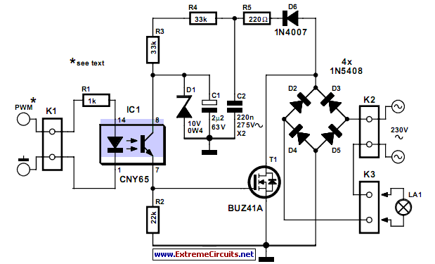
This circuit demonstrates that dimmers designed for mains voltage do not always require a triac. In this case, a MOSFET (BUZ41A, 500 V/4.5A) is utilized in a diode bridge configuration. The described circuit employs a MOSFET as the primary switching...
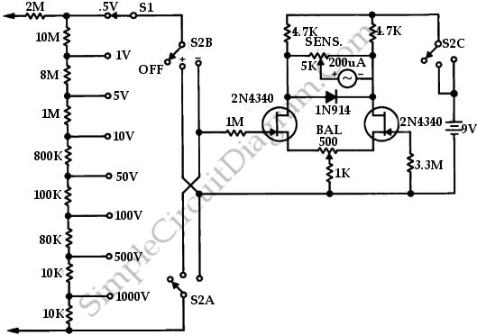
This is a circuit of a FETVM (Field Effect Transistor Voltmeter). The function of the VTVM (Vacuum Tube Voltmeter) is replaced by the FETVM while eliminating the conventional line cord instrument. The FETVM circuit employs field effect transistors (FETs) to...
The mixer allows for the addition of multiple channels as needed. This can be accomplished by simply duplicating the input sections that are clearly indicated on the schematic. One variant of this mixer was observed to have 25 inputs. The...