
FETVM-FET Voltmeter

The FETVM circuit employs field effect transistors (FETs) to measure voltage levels with high impedance and accuracy. The primary advantage of using FETs in this application is their high input impedance, which minimizes the loading effect on the circuit being tested. This characteristic allows the FETVM to measure voltages without significantly altering the circuit's behavior.
The circuit typically includes an input stage that consists of a FET configured as a voltage follower, which provides isolation between the input and the subsequent stages. The output from this stage is then fed into an amplifier that further processes the signal. The gain of the amplifier can be adjusted to accommodate various voltage ranges, ensuring versatility in measurement.
In addition to the input and amplification stages, the FETVM circuit may incorporate a display mechanism, such as an analog meter or a digital readout, to present the measured voltage. The choice of display technology can affect the circuit's overall design, particularly in terms of power requirements and signal conditioning.
Power supply considerations are also crucial in the design of the FETVM. The circuit may utilize battery power to enhance portability and eliminate the need for a line cord, aligning with the goal of providing a more convenient and flexible measurement tool.
Overall, the FETVM circuit represents a modern approach to voltage measurement, leveraging the advantages of field effect transistors to achieve high precision and minimal impact on the circuit under test.This is a circuit of FETVM-FET Volmeter. The function of the VTVM is replaced by the FTEVM while at the same time ridding the usual line cord instrument. This.. 🔗 External reference
Related Circuits
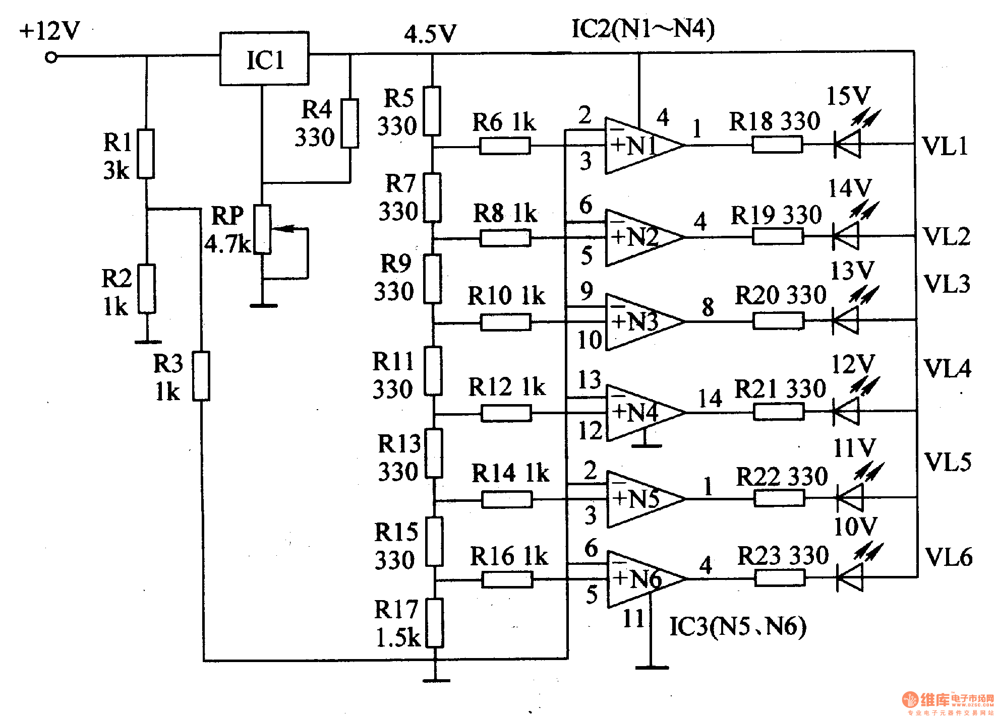
This document introduces an LED car voltmeter constructed using the op-amp LM312 and LED components. It is designed to display six voltage levels ranging from 10V to 15V, with each level representing a 1V increment. The working principle of...
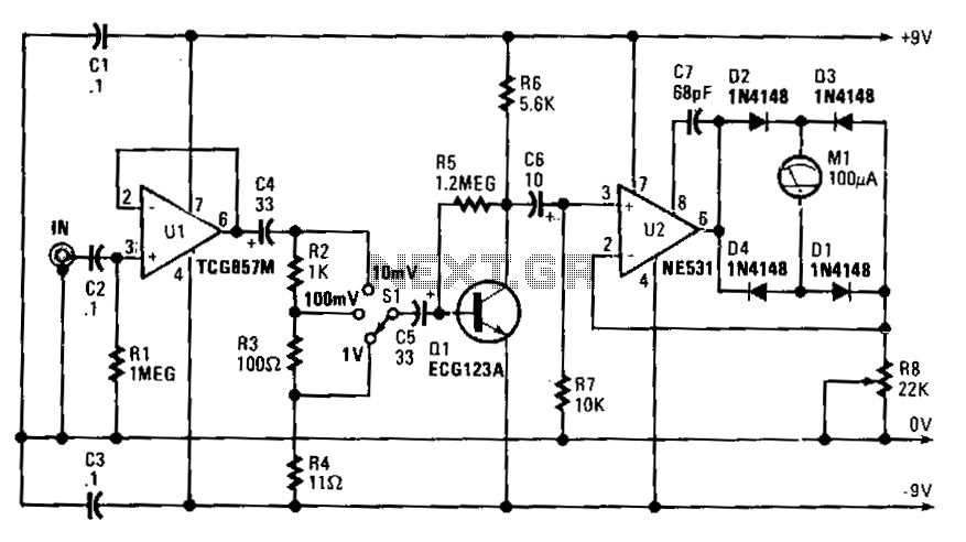
Capacitor C4 couples the output of U1 to a simple attenuator, which provides a loss of 0 dB, 20 dB, or 40 dB, depending on the setting of range switch S1. The circuit's sensitivity is 10 V rms for...
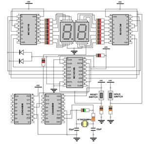
The ICL7107 is a 3 1/2 digit LED analog-to-digital converter (A/D converter). It features an internal voltage reference, high-isolation analog switches, sequential control logic, and display drivers. The ICL7107 is designed to convert analog signals into digital representations with a...
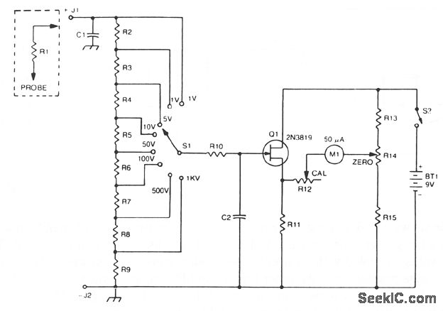
The 2N3819 FET serves as a solid-state voltage output meter (VOM). In this configuration, the 2N3819 functions as a cathode follower. The bias offset, or meter null, is achieved using resistors R14 and R12, while the full-scale calibration is...
The WPG DM8168 DaVinci high-definition video System on Chip (SoC) offers multiple DVR/NVR surveillance solutions, utilizing the MT9M033 image sensor as a key component in safety monitoring systems. This solution is complemented by Conexant's line of multi-channel video surveillance...
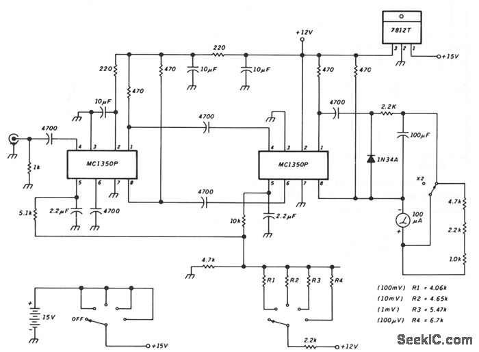
This schematic illustrates a peak-reading diode voltmeter that is powered by two amplification stages. A 100 µF capacitor is utilized to create a substantial time constant, which ensures effective damping of the meter. The restricted differential output voltage, combined...