
Field disturbance sensor-alarm

The circuit utilizes two light-dependent resistors (LDR1 and LDR2) to detect variations in ambient light levels. LDRs are passive components that exhibit a change in resistance based on the intensity of light falling on them; their resistance decreases as light increases. This property is essential for the operation of the alarm system.
In this configuration, LDR1 and LDR2 are arranged in a voltage divider setup. The voltage across one of the LDRs is monitored and compared to a reference voltage. When ambient light levels change, the resistance of the LDRs alters, leading to a corresponding change in the voltage across them. This change is critical for triggering the alarm.
A PNP transistor is employed to amplify the signal from the LDRs. The base of the PNP transistor is connected to the junction of the voltage divider formed by LDR1 and LDR2. When the voltage at the base exceeds a certain threshold, the transistor turns on, allowing current to flow from the collector to the emitter. This action activates the alarm system, indicating a significant change in ambient light.
To ensure proper operation, it is important to select a suitable PNP transistor that can handle the expected current and voltage levels in the circuit. Additionally, resistors may be included in the circuit to limit current and protect the components from damage.
Overall, this alarm system effectively utilizes the properties of LDRs and a PNP transistor to create a responsive and reliable light-triggered alarm.The change in ambient light triggers the alarm by changing resistance of LDRl and LDR2. use any regular pnp transistor.
Related Circuits

This detector circuit is sensitive to low-frequency electromagnetic radiation and can detect hidden wiring or the field around a transformer. The pickup is achieved using a radial type inductor, which serves as a probe that responds effectively to low-frequency...

A three-dimensional surround sound Ambisonic recording can be captured using a tetrahedrally arranged quartet of cardioid pattern microphone capsules connected to some simple circuitry to convert the outputs to a standard B-format signal. B-format signals represent a 3D soundfield...
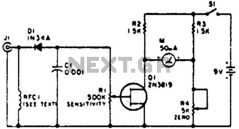
This circuit employs a FET as a DC amplifier within a bridge configuration. Resistor R4 is adjusted for meter nulling with switch J1 short-circuited. Any surplus 50-mA meter can be utilized in this circuit. RFC1 represents a suitable RF...

A waveguide directs energy onto a crystal detector during operation. The diode utilized is designed for X-band operation. The waveguide consists of a 1-inch piece of plastic tubing with flared ends. The plastic surface is treated with an electroless...
One cannot expect high performance from a simple detector-based meter. The sensitivity is only sufficient to provide a basic understanding of the power output that the transmitter can achieve. A detector-based meter operates on the principle of rectifying the RF...
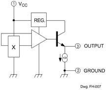
The Hall Effect sensor generates a voltage that is proportional to the strength of the magnetic field it detects. This sensor consists of a silicon layer with two electrodes on either side. In the absence of a magnetic field,...