
Low cost microwave field strength meter

The described circuit involves a waveguide system that effectively channels electromagnetic energy towards a crystal detector, which is critical for applications in microwave frequencies, particularly within the X-band range (8 to 12 GHz). The waveguide, constructed from a 1-inch diameter plastic tubing, is designed with flared ends to minimize reflection losses and improve the coupling efficiency with the incoming signal.
The electroless copper coating applied to the inner surface of the plastic tubing serves to enhance the conductivity of the waveguide, allowing for efficient transmission of the microwave signals. This treatment is essential as plastic itself is an insulator, and the copper layer facilitates the propagation of the electromagnetic waves through the waveguide without significant attenuation.
For effective operation, the measurement device, or meter, must be calibrated. This is achieved by placing it in a known electromagnetic field or by comparing its readings with those of a calibrated reference meter. Calibration ensures that the readings obtained from the meter are accurate and reliable.
The operational procedure for utilizing the meter involves several steps. First, the meter should be pointed away from the signal source to avoid interference during calibration. The user must then select the desired measurement range on the device, which determines the sensitivity and scale of the readings. Adjusting the zero control is crucial to ensure that the meter reads zero when no signal is present, which establishes a baseline for subsequent measurements.
Once the meter is calibrated, the waveguide can be directed towards the signal source. The field strength can then be read directly from the meter, providing the user with real-time data on the strength of the electromagnetic field being measured. This setup is widely used in applications such as radar, telecommunications, and various research fields involving microwave technology.When operating, a waveguide directs energy onto a crystal detector. The diode shown is for X-band operation. The waveguide is a 1H inch piece of plastic tubing with the ends flared. The plastic is coated with an elec-troless copper solution to provide a conducting surface. The dimensions are not critical. For calibrated readings, the meter is placed in a known field or else compared to a calibrated meter To operate the meter, point it away from the signal. Switch the meter to the desired range, and adjust the zero control for a 0 reading. Then point the waveguide at the signal, and read field strength directly.
Related Circuits
A digital thermometer is being planned for construction using an ATmega8 microcontroller and an LM335 temperature sensor. Guidance is sought on how to proceed with the project, particularly concerning the display components. The digital thermometer circuit utilizes the ATmega8 microcontroller,...

A high-input-resistance operational amplifier (op-amp), a bridge rectifier, a microammeter, and several discrete components are necessary to implement this versatile circuit. This circuit can measure DC, AC RMS, AC peak, or AC peak-to-peak voltage by simply altering the resistor...
This instrument requires two precision components: A precision capacitor and a precision inductor. You only need to start with one precision component, either the reference capacitor or the reference inductor, and using this meter, you can select or adjust...
The following circuit illustrates the sensor circuit of an analog line follower robot. Features include control by a microcontroller and a sensor circuit. The sensor circuit for an analog line follower robot is designed to detect the presence of a...
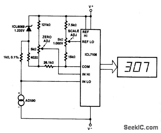
This circuit allows for zero adjustment as well as slope adjustment. The ICL8069 brings the input within the common-mode range, while the 5 K pots trim any offset at 218 °K (-55 °F) and set the scale factor. The...
A highly effective method for providing continuous and direct indication of electrostatic voltmeter (ESV) readings, even in large lecture halls, is to integrate this instrument with a tonal voltmeter (TVM). The TVM emits an audible tone of constant amplitude,...