
Filter Choke Analyzer

The described circuit operates as a power supply filter, employing both passive and active components to ensure a stable output voltage with minimal ripple. The large filter capacitor at the rectifier output serves to smooth the rectified voltage, while the electronic regulator maintains a consistent voltage level, compensating for any variations due to load changes or ripple from the rectification process.
The use of an LC filter in high-current applications is critical, as it provides superior filtering characteristics compared to RC filters, particularly in maintaining audio fidelity in Hi-Fi systems. The inductor, with its iron core, is designed to handle significant current without saturating, which is essential for performance in demanding applications. The calculations of inductance and reactance are vital for ensuring that the inductor operates efficiently within its specified limits, preventing distortion and loss of signal integrity.
When testing inductors, the circuit configuration allows for a clear understanding of the inductor's behavior under both AC and DC conditions. The transformer serves as an isolation barrier, preventing interference from line voltage while allowing for accurate measurements of voltage and current. This setup is beneficial for evaluating the performance of vintage filter chokes, which may not have readily available specifications.
Overall, this power supply design exemplifies the importance of both passive and active components in achieving high-performance electronic circuits, especially in applications where signal integrity and power efficiency are paramount. The careful selection and testing of components, such as inductors and capacitors, play a crucial role in ensuring the reliability and effectiveness of the power supply system.The familiar transistor power supply has one big mother of a filter capacitor on the rectifier output followed by an electronic regulator which regulates out all voltage variations including ripple. In vacuum tube days only the very tip top of the line test equipment (Hewlett Packard, Tektronics, General Radio, etc) used electronic regulators.
So it was necessary to find a way to filter out most of the ripple using passive components (not tubes). In many devices such as low cost radios and phonographs the designers managed to use resistor-capacitor RC filters but if the current drawn by the circuit was large and the application demanding, such as a Hi-fi power amplifier, the power supply needed an inductor-capacitor (LC) filter. An inductor needs to have many turns of wire wound on an iron core. The wire must be heavy enough to have a low enough resistance so it can conduct the direct current without dissipating an excessive, usually five watts or less, amount of power.
The core had to have enough iron in it so as not to saturate at the maximum specified current. Filter chokes are getting hard to find they mostly are seen at electronic flea markets (hamfests) and from dealers on the net who specialize in antique electronic parts. If you`re a retread like me you may have some stored in your basement or garage. It is very likely these old chokes whether in your garage or from a flea market won`t be marked with specifications.
Don`t despair. Ve have vays of finding out zese sings. It`s not enough to just measure the inductance of a choke. You need to know how it behaves when carrying a mixture of AC and DC. The simplified circuit is shown here. The transformer isolates the test circuit from the line and provides some step down. The secondary delivers very little Alternating Current but it must be capable of passing the DC without overloading the winding or saturating the transformer`s core. The value in amps of the alternating current can be found by dividing the voltage across the resistor by the resistance of the resistor.
In this example that`s pretty easy. Next the reactance of the inductor can be found by dividing the alternating voltage by the AC. After the reactance is known the inductance can be calculated from the formula where XL is the inductive reactance and f is the line frequency of 60 Hz (50 outside U S and Canada). When the DC power supply is turned up from zero the inductor`s core will begin to saturate, the inductance will be decreased, as will the reactance and the AC will rise.
The new value of inductance can be determined by repeating the calculation. The AC voltmeters are not phase sensitive. As you know the current lags the voltage by 90 degrees in an inductive circuit. In a true inductance meter the meter which reads the current should only respond to current which is 90 degrees out of phase with the applied voltage. Some inductors have a small reactance to resistance ratio or Q. A filter choke, by definition, has a relatively high Q even at 60 cycles although they are intended to operate at 120 cycles.
This meter doesn`t know the difference between inductance and resistance but it makes no difference as long as it is used as intended. This fact is used to calibrate the instrument. Both AC voltmeters must not respond to DC. The DC is necessary 🔗 External reference
Related Circuits
The input signal is processed with an electronic low-pass filter to eliminate all frequencies above the Nyquist frequency, which is half of the sampling rate. This process is essential to prevent aliasing during sampling and is referred to as...
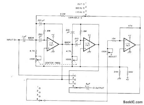
The circuit utilizing Optical Electronics 9803 operational amplifiers separates an audio frequency (AF) input signal into two outputs. The low-pass output allows frequencies from DC up to 10 Hz, while the high-pass output encompasses frequency content above 10 Hz,...
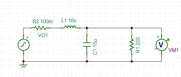
An inductor is used in series with a decoupling capacitor, forming a series LC circuit. One of the characteristics of LC circuits is their resonant frequency. A model of this LC circuit was created with a purely resistive load...
The RF amplifiers utilize noiseless feedback through the drain-gate capacitance, incorporating an inductor in the source lead to achieve the necessary 90-degree phase shift between the gate voltage and channel current. The first RF amplifier provides approximately 4 dB...

The inquiry pertains to whether a specific circuit will invert the input signal. The operational amplifier (op-amp) is single-supplied with a voltage of 5V, and the input signal varies between 0V and 5V. The question arises regarding the output...
This circuit filters noise, such as glitches and contact bounce, from digital signals. It can be easily adjusted for a wide range of noise frequencies. The circuit's output changes state only if the input differs from the output long...