
RF amplifier and filter for 144 MHz
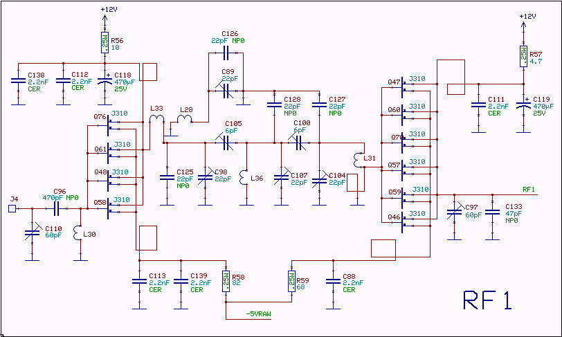
The RF amplifier circuit described employs a sophisticated design to ensure optimal performance in radio frequency applications. The use of noiseless feedback through the drain-gate capacitance is a key feature, enhancing linearity and minimizing distortion. The inductor placed in the source lead is crucial for achieving the required phase shift, which is essential for maintaining signal integrity and coherence throughout the amplification process.
The first stage of amplification delivers a gain of approximately 4 dB while maintaining a low noise figure of about 2 dB. This initial amplification stage is followed by a filter that attenuates the signal by approximately 3 dB, which is a common practice to eliminate unwanted frequency components and improve overall signal quality before further amplification.
The second RF amplifier stage, equipped with a greater number of transistors, effectively doubles the gain to an additional 4 dB, culminating in a total gain of around 5 dB. This staged amplification approach is beneficial for maintaining signal fidelity and achieving desired output levels without introducing excessive noise.
The third-order intercept points (IP3) are critical metrics in assessing the linearity and performance of RF amplifiers. The input IP3 of +35 dBm indicates the level at which intermodulation distortion begins to significantly affect the output signal. The output IP3 of +40 dBm is particularly noteworthy, as it ensures that the mixer can handle the signal without degradation, overcoming the losses associated with load resistors at the mixer input.
The transfer function represented in Figure 3 illustrates the frequency response of the RF amplifier and filter section, which has been meticulously measured using a network analyzer. This measurement approach, involving an extra winding on transformer TR6, allows for precise characterization of the circuit's performance, ensuring that the RX144 unit operates efficiently within its intended frequency range. Such detailed analysis is essential for optimizing the design and ensuring reliable operation in practical applications.The RF amplifiers use noiseless feedback through the drain-gate capacitance with an inductor in the source lead to provide the necessary 90 degree phase shift between gate voltage and channel current. The first RF amplifier gives about 4dB gain with a noise figure of about 2dB. The filter attenuates by about 3dB, then the second RF amplifier with twice as many transistors gives another 4dB gain for a total gain of about 5dB. The third order intercept point at the input is +35dBm, the output IP3 is +40 dBm which is required to overcome the losses of the load resistors at the mixer input and make sure that the IP3 of the mixer itself dominates the IP3 of the entire RX144 unit. Fig. 3. The transfer function of the RF amplifier and filter section of the RX144 unit. This curve is measured with a network analyzer coupled to the mixer input by an extra winding on TR6.
🔗 External reference
Related Circuits
This transmitter is PLL controlled and the frequency is very stable and can be programmed digitally. The transmitter will work from 88 to 108 MHz and the output power is up to 500mW. With minor changes the frequency can...
The 300B tube single-ended Class A amplifier circuit is as follows: The 300B tube single-ended Class A amplifier is a high-fidelity audio amplification circuit that utilizes a 300B vacuum tube as the primary amplification element. This design is characterized by...
A simple 1 kHz, 6 Vpp sine wave generator was constructed using a few operational amplifiers and passive components. The goal was to evaluate the quality of the generated sine wave, which is fundamentally a wave-shaped triangle wave. The...

This circuit turns off an amplifier or any other device when a low-level audio signal fed to its input is absent for at least 15 minutes. By pressing P1, the device is powered on, supplying power to any appliance...
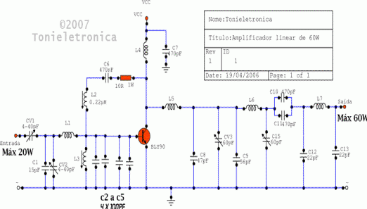
This circuit functions as an RF power amplifier designed to operate with a power supply capable of delivering 13 volts at a current of 10 amperes. Careful assembly of the power source is essential. It utilizes a shielded transformer...
A wide range frequency meter is a useful tool for an electronics lab. This project describes a frequency meter based on the AT90S231 microcontroller that can measure input frequencies up to 50 MHz. The measured frequency is displayed on...
Warning: include(partials/cookie-banner.php): Failed to open stream: Permission denied in /var/www/html/nextgr/view-circuit.php on line 713
Warning: include(): Failed opening 'partials/cookie-banner.php' for inclusion (include_path='.:/usr/share/php') in /var/www/html/nextgr/view-circuit.php on line 713