
Police Siren circuit diagram

The police siren circuit typically employs two 555 timer integrated circuits (ICs) configured in astable mode to generate a square wave output. The first 555 timer is responsible for generating a basic frequency that mimics the rising and falling tones of a police siren. The output frequency can be adjusted by varying the resistor and capacitor values connected to the timer.
The second 555 timer acts as a modulator, creating a frequency that varies over time to produce the characteristic sound of a siren. This modulation can be achieved by connecting a potentiometer in series with the timing components of the second timer, allowing for real-time adjustments to the pitch and interval of the tone.
The output from both timers is typically fed into a power amplifier stage, which drives a speaker or piezo buzzer to produce audible sound. Additional components may include diodes for protection against reverse polarity and capacitors for filtering any noise from the power supply.
To construct this circuit, the following components are generally required:
- Two 555 timer ICs
- Resistors for timing configuration (typically in the range of kilo-ohms)
- Capacitors for timing and filtering (usually in the microfarad range)
- A potentiometer for adjustable frequency modulation
- A speaker or piezo buzzer for sound output
- A power supply, often a 9V battery or equivalent DC source
The circuit layout should be carefully designed to minimize interference and ensure stable operation. Proper grounding and decoupling techniques should be employed to enhance performance and reliability. This police siren circuit is a popular project for electronics enthusiasts and can be used in various applications where audible alerts are required.Police Siren circuit diagram. This circuit produces a sound similar to the police siren. It makes use of two 555 timer ICs used as. 🔗 External reference
Related Circuits
Gadget Master provides the latest updates on capacitance circuits in a compilation of capacitance circuit projects and websites tailored for electronics designers, scientists, and engineers. Capacitance circuits are fundamental in various electronic applications, serving critical roles in timing, filtering, and...
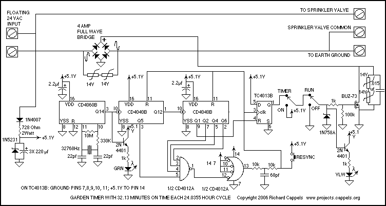
The resulting timer circuit is made from a CD4060, includes an oscillator and a 14 stage binary counter, two CD4040's, which are 12 stage binary counters, a CD4012 Dual Nand gate and a CD4013 Dual D Latch. The CD4060...
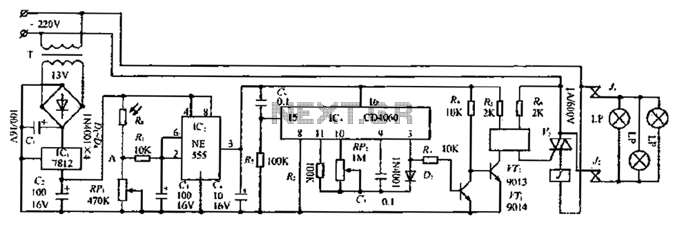
The circuit consists of three parts: a light control section, a time control section, and a power supply section. The light control section utilizes a photoresistor (Rg) and a variable resistor (RP) to detect light levels. During the day,...
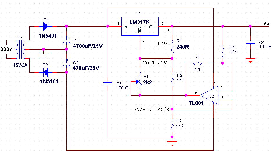
The LM317 is an adjustable, positive 3-terminal voltage regulator capable of supplying 100 mA (for RA87U control) or 1.5 A (for Order Code UF27E and N61CA) across an output voltage range of 1.2 V to 37 V. These voltage...
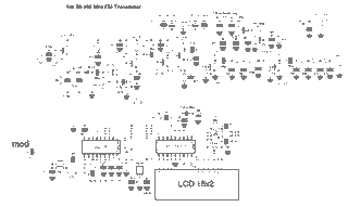
Here's PLL FM transmitter circuit from china. This circuit uses the familiar 2SC1971 for final power amplifier stage. The PLL controller of the FM transmitter use SAA1057 and PIC16F628 (download HEX file). More: If want to change the active...
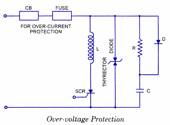
Silicon Controlled Rectifiers (SCRs) are sensitive to high voltage, over-current, and transients. To ensure satisfactory and reliable operation, they must be protected against such abnormal operating conditions. Due to the complexity and cost of protection mechanisms, devices with ratings...